


Additional UPS Features
31
Powerware
®
5125 Tower (1000–2200 VA)User’sGuide RevB www.powerware.com
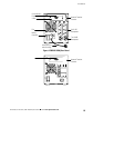
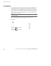
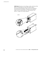
Network Transient Protector
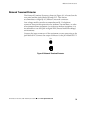
The Network Transient Protector, shown in Figure 16, is located on the
rear panel and has jacks labeled IN and OUT. This feature
accommodates a single RJ-45 (10BaseT) network connector.
Low voltage models can also accommodate an RJ-11 telephone
connector that provides protection for modems, fax machines, or other
telecommunications equipment. As with most modem equipment, it is
not advisable to use this jack in digital PBX (Private Branch Exchange)
environments.
Connect the input connector of the equipment you are protecting to the
jack labeled IN. Connect the output connector to the jack labeled OUT.
Out
In
Figure 16. Network Transient Protector