


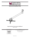


EST150
Installation Instructions Visit the Premier Mounts website at http://www.premiermounts.com Page 11
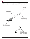
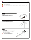
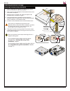
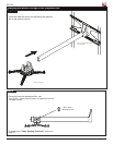
Step 5
1) Position the legs accordingly for best conguration.
You may raise or lower each leg independently by
turning the leveling barrels.
2) Secure the legs to the mount carriage by screwing
M6 x 12mm security screws into the M6 square nut
(do not overtighten) on the mounting legs.
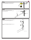
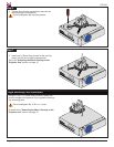
3) Verify the position of the integrated sliding M6 square
nut in the mounting leg relative to a nearby slot on the
mount carriage.
If the M6 square nut is not aligned with any slot, you
can use any thin implement, such as a toothpick, to
nudge it into alignment.
Sliding M6
Square Nut
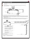
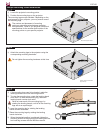
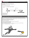
1) Identify the projector’s approximate front-to-back
center of gravity. Place your hands on each side of
the projector and gently lift it an inch from the surface
on which it is resting. Carefully adjust your grip on the
projector until it seems balanced from front-to-back.
Mentally note the apparent center of gravity.
2) Identify the projector’s approximate side-to-side
center of gravity. Place your hands on the front and
back of the projector and gently lift it an inch from the
surface on which it is resting. Carefully adjust your
grip on the projector until it seems balanced from
side-to-side. Mentally note the apparent center of
gravity.
3) Make sure the mount carriage is as close as possible
to the projector’s center of gravity.
Step 4
Side-to-Side
Center of Gravity
Front-to-Back
Center of Gravity
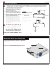
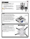
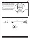
Mounting Hardware Too Long?
The depth of some projector mount points may
prevent you from tightening the M2.5 and M3
mounting hardware.
You can reduce the length of the M2.5 and
M3 mounting hardware by stacking up to a
maximum of ve (5) M3 at washers inside the
leveling barrel.
Avoid stacking too many M3 washers; the
mounting hardware must thread into the
projector mount point at least four (4) complete
turns.