


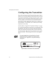

Configuring the Transmitter
22 ProjectionLink User & Installation Guide
Configuring the Transmitter
One of the key features of the ProjectionLink system is that it
allows you to use many different input devices with most Prox-
ima projectors. But before you begin using the system, you’ll
need to set up the transmitter to match the projector you will
be using. Again, we recommend you set up the transmitter
and receiver with the appropriate cables prior to making your
final installation. This will allow you to make any fine tuning
adjustments more easily.
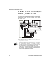
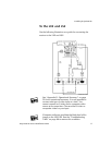
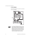
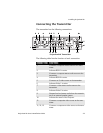
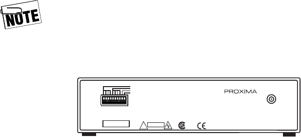
Use the tables in “Appendix C: Dip-Switch Settings” on page
51 to set the dip-switches on the back of your transmitter. Dip-
switches one, two, three, four, and ten control the projector
family. Dip-switches five through eight control the baud rate
for the transmitter. Dip-switch nine controls the service mode
for the transmitter. These settings will work for most applica-
tions
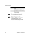
For typical applications, dip-switches five through
eight should not be modified. For custom control
applications, see “Appendix C: Dip-Switch Settings”
on page 51.
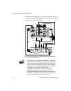
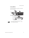
Dip-switches on the back of the transmitter
Projection Link
MODEL NO. PL-300T
Proxima Corporation
9440 Carroll Park Drive
San Diego, Ca 92121-2298
www.proxima.com
MN8, a trade mark of INT LABS, Inc.
Made in USA
POWER
9VAC, 1A
This device complies with Part 15 of the FCC Rules. Operation is
subject to the following two conditions (1) this device may not cause
harmful interference, and (2) this device must accept any interference
received including interference that may cause undesired operation.
See user’s guide or Proxima
website for dipswitch settings
for your Proxima projector.
SERIAL NO.
Product Family
Baud Rate
ISP
Reserved
!
CAUTION
c
us