


6 – Removal/Replacement
Power Supply Removal and Replacement
59265-00 A 6-3
A
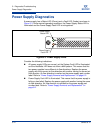
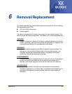
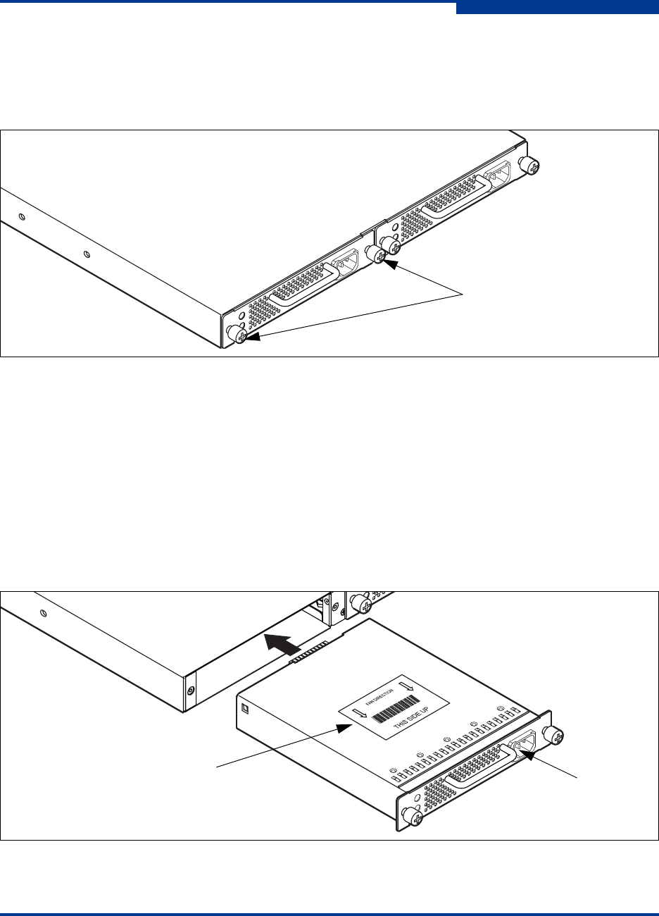
To remove a power supply, unplug the power supply and loosen the two knurled
fasteners with a cross-head screw driver as shown in Figure 6-1. Grasp the power
supply handle and pull firmly to disengage the modular connector. Slide the power
supply out of its bay.
Figure 6-1 Power Supply Removal
1. Confirm that the Heartbeat LED is showing the normal 1 blink per second.
This allows the switch to correctly report power supply status.
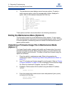
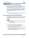
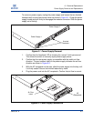
2. Confirm that the new power supply is compatible with the switch air flow
direction. The part number label on the power supply indicates the air flow
direction as shown in Figure 6-2.
3. With the AC receptacle on the right, slide the power supply into the bay until
it is firmly seated. Secure the knurled fasteners by hand.
4. Plug the power cord into the AC receptacle. Confirm that air flow is correct.
Figure 6-2 Power Supply Installation
Knurled
Fasteners
Power Supply 1
Power Supply 2
Air Flow
Label
AC
Receptacle