


4 – Installation
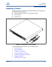
Installing a Switch
59265-00 A 4-11
A
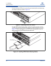
To power up the switch, connect the power cords to the power supply receptacles
on the back of the switch chassis and to a grounded AC outlet. To provide
redundancy in the event of an AC power circuit failure, connect the switch power
supplies to separate AC circuits. The switch responds in the following sequence:
1. The chassis LEDs (Input Power, Heartbeat, System Fault) illuminate
followed by all port Logged-In LEDs.
2. After a couple seconds the System Fault LED is extinguished while the Input
Power LED and Heartbeat LED remain illuminated.
3. After approximately one minute, the POST executes and the Heartbeat LED
is extinguished.
4. After about another minute, the POST is complete, all LEDs are
extinguished except the Input Power LED and the Heartbeat LED:
The Input Power LED remains illuminated indicating that the switch
logic circuitry is receiving DC voltage. If not, contact your authorized
maintenance provider.
The Heartbeat LED indicates the results of the POST. The POST tests
the condition of firmware, memories, data-paths, and switch logic
circuitry. If the Heartbeat LED blinks steadily about once per second,
the POST was successful, and you can continue with the installation
process. Any other blink pattern indicates that an error has occurred.
Refer to “Heartbeat LED Blink Patterns” on page 5-3 for more
information about error blink patterns.