


2 – General Description
Chassis Controls and LEDs
2-2 59265-00 A
S
Chassis Controls and LEDs
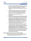
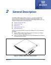
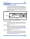
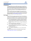
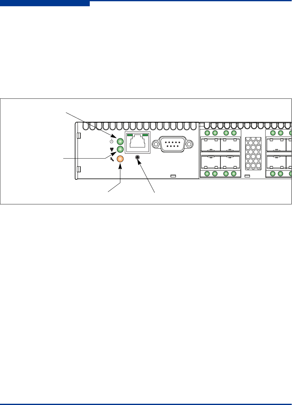
The chassis LEDs provide information about the switch’s operational status.
These LEDs include the Input Power LED (green), Heartbeat LED (green), and
the System Fault LED (amber) as shown in Figure 2-2. The Maintenance button
shown in Figure 2-2 is the only chassis control and is used to reset a switch or to
recover a disabled switch. To apply power to the switch, plug the power cords into
the switch AC power receptacles, located on the back of the switch, and into a
100–240 VAC power source.
Figure 2-2 Chassis LEDs and Controls
Input Power LED (Green)
The Input Power LED indicates the voltage status at the switch logic circuitry.
During normal operation, this LED illuminates to indicate that the switch logic
circuitry is receiving the proper DC voltages. When the switch is in maintenance
mode, this LED is extinguished.
Heartbeat LED (Green)
The Heartbeat LED indicates the status of the internal switch processor and the
results of the POST. Following a normal power-up, the Heartbeat LED blinks
about once per second to indicate that the switch passed the POST and that the
internal switch processor is running. In maintenance mode, the Heartbeat LED
illuminates continuously. Refer to “Heartbeat LED Blink Patterns” on page 5-3 for
more information about Heartbeat LED blink patterns.
System Fault LED (Amber)
The System Fault LED illuminates to indicate that a fault exists in the switch
firmware or hardware. Fault conditions include POST errors, over-temperature
conditions, and power supply malfunctions. The Heartbeat LED shows a blink
code for POST errors and over temperature conditions. For more information,
refer to “Heartbeat LED Blink Patterns” on page 5-3.
Maintenance
Button
Input Power LED
(Green)
Heartbeat LED
(Green)
System Fault LED
(Amber)