6
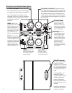
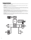
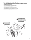
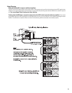
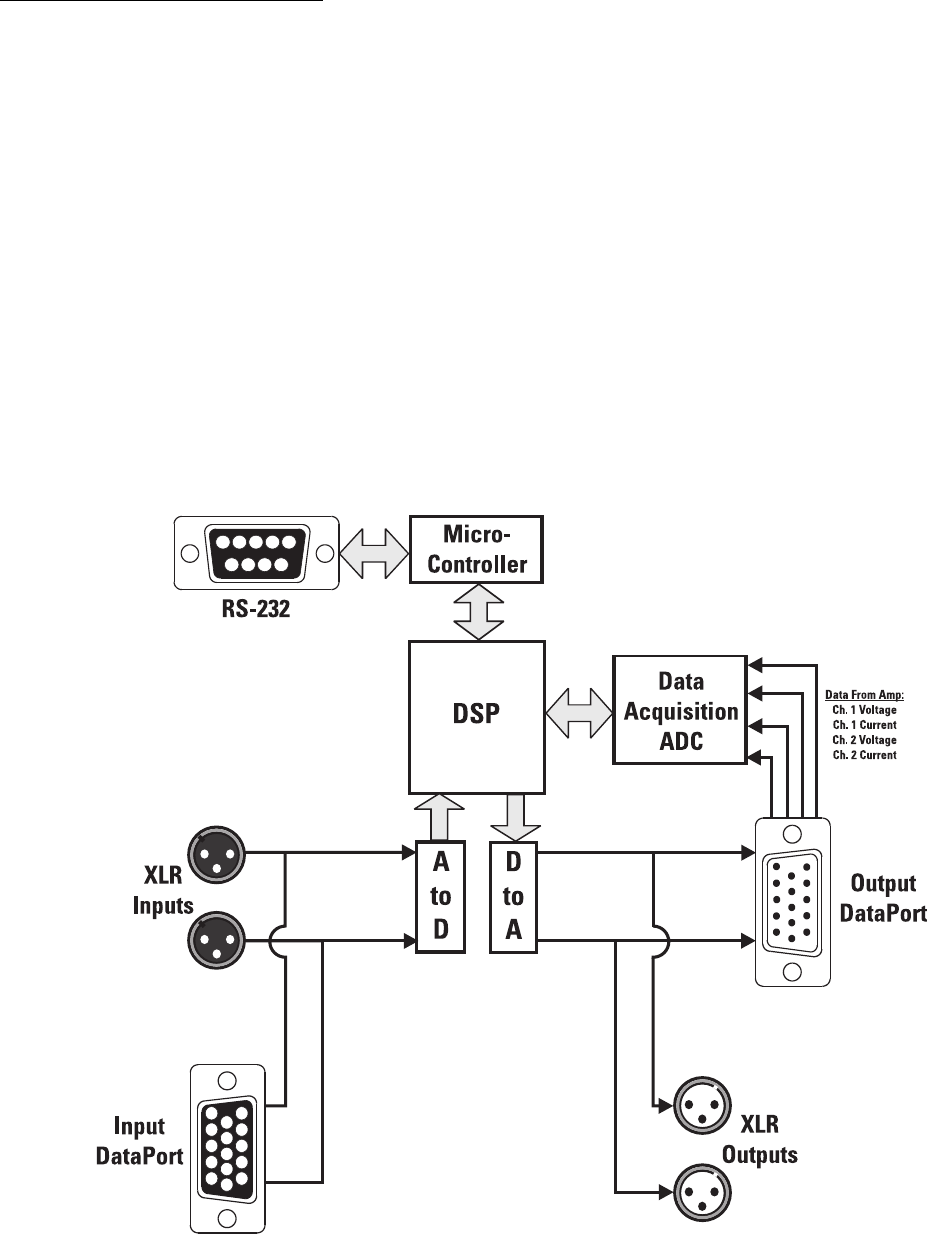
Introduction- Block Diagram
Input Stage- Inputs are electronically balanced and RF filtered. The input sensitivity is software-selectable and any large signals are
prevented from destroying the A-to-D by a diode.
Output Stage- The output is buffered and then filtered to remove high-frequency sampling artifacts. Output sensitivity is software-
selectable and available from both sets of outputs simultaneously.
Data Acquisition- The data acquisition A-to-D samples the output voltage and current of both amplifier channels. This data is used
for amplifier output power limiting. Amplifier clip and protect-mode status data is also sampled. Power, protect/clip indication, and out-
put power limiting is not possible on non-DataPort amplifiers or “V2” DataPort amplifiers.
Contact Closure Trigger Input- Pin 9 of the RS-232 can be used as a trigger input for operating software “objects”, such as
“Switched Gain”. It’s TTL compatible: pulling this pin to ground through a maximum impedance of 1.3k ohms forces a general I/O pin of
the DSP to a logic-low condition. The Signal Manager software can use this “event” to change gain settings or Preset mode. Refer to
the Signal Manager software Help file for available applications of the Contact Closure Trigger Input.
Power Supply- The DSP module is normally provided power through its DataPort connection from the amplifier. If you are using an
older amplifier or an amplifier that does not have a DataPort, an external power jack is provided on the DSP module. If external power
is required, use QSC’s DPX-1 accessory power supply.


