


10.1 DTE Configuration
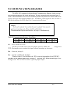
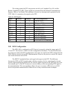
The MPA-100 is configured as a DTE device by correctly setting jumper packs J2, J11
and J12. See Section 5, Table 3 for this configuration information.
The control signals the DTE can generate are Request To Send (RTS) and Data Terminal
Ready (DTR). It can receive the signals Carrier Detect (CD), Clear To Send (CTS), and Data Set
Ready (DSR). All the control signals are handled through channel A of the SCC, with the
exception of the DSR signal, which is received on the DCDB pin (pin 21) on channel B.
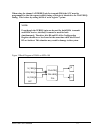
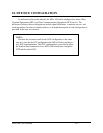
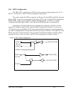
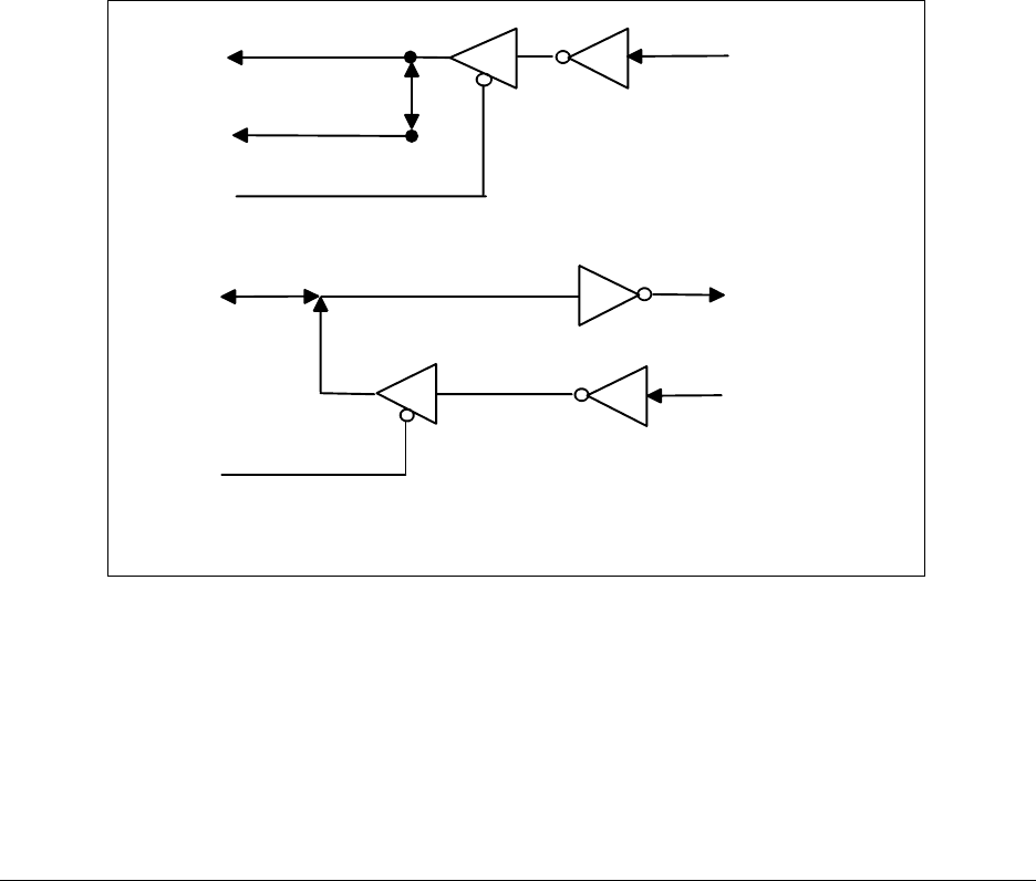
Depending on TCKEN (bit D2 of the Communications Register), the DTE can either
transmit its Transmit Clock (TCLK) from the TRXCA pin (pin 14) of the SCC, or receive its
TCLK on the same pin. RCKEN (bit D3 of the Communications Register) is always deasserted
on a DTE configured MPA-100; therefore the DTE can receive its Receive Clock (RCLK) on the
RTXC pins (pin 12 & 28) of the SCC but, as per the EIA-232D specification, the DTE cannot
transmit its receive clock. For clarity, the DTE clock configuration is shown in Figure 4.
Figure 4 DTE Clock Configuration
RTXCA
RTXCB
RXCLK (DCE)
RCKEN
(RCLK)
TRXCA
TXCLK (DTE)
TXCLK (DCE)
TCKEN
(TCLK)
MPA-100 User's Manual 10-2