Control signals the DCE can generate are the Clear to Send (CTS), Carrier Detect (CD),
and Data Set Ready (DSR). It can receive the signals Data Terminal Ready (DTR) and Ready to
Send (RTS). All the control signals are handled through channel A of the SCC, with the
exception of the CD signal, which is generated on the DTR/REQB pin (pin 24) of the SCC.
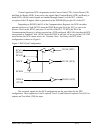
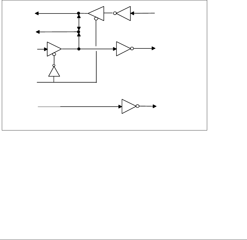
Depending on RCKEN (bit D3 of the Communications Register), the DCE can either
transmit its Receive Clock (RCLK) from the TRXCB pin (pin 26) of the SCC, or receive its
Receive Clock on the RTXC pins (pins 12 and 28) of the SCC. TCKEN (bit D2 of the
Communications Register) is always asserted on a DTE configured MPA-100; therefore the DCE
can transmit its Transmit Clock (TCLK) from the TRXCA pin (pin 14) but, as per the EIA-232D
specification, the DCE cannot receive its Transmit Clock. For clarity, the DCE clock
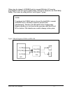
configuration is shown in Figure 5.
Figure 5 DCE Clock Configuration
TRXCA
RTXCA
RTXCB
RXCLK (DCE)
TXCLK (DTE)
TRXCB
RCKEN
TXCLK (DCE)
(RCLK)
(TCLK)
The test mode signals for the DCE configuration are the same those for the DTE
configuration. These signals are Local Loopback Test (LL) and Remote Loopback Test (RL) for
outputs and Test Mode (TM) for input.
MPA-100 User's Manual 10-4


