


2. Hardware Installation
If the default address and interrupt settings are sufficient, the QS-100D can be
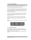
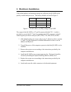
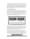
quickly installed and put to use. The factory defaults are listed in Figure 3.
3318 hexSerial 4
3310 hexSerial 3
3308 hexSerial 2
3300 hexSerial 1
IRQADDRESSPORT
Figure 3 --- Default address and IRQ settings for QS-100D
The output of the QS-100D is a 37-pin D-connector labeled CN1. A cable is
provided to convert the D-37 into four standard male D-25 connectors with all
control signals provided to each port (RTS, DTR, CTS, DSR, DCD, and RI).
1. If the default settings are correct, skip to step 2, otherwise refer to sections
2.1 and 2.2 of this document for detailed information on how to set the
address and IRQ level.
2. Turn off the power of the computer system in which the QS-100D is to be
installed.
3. Remove the system cover according to the instructions provided by the
computer manufacturer.
4. Install the QS-100D in any vacant expansion slot. The board should be
secured by installing the Option Retaining Bracket (ORB) screw.
5. Replace the system cover according to the instructions provided by the
computer manufacturer.
6. Attach and secure the cable connectors to the desired equipment.
QS-100D User's Manual 2-1