


6 External Connections
The QSC(LP)-200/300 provides four differential communication signals per channel. The
two output signals are Transmit Data (TxD) and Auxiliary Output (AUXOUT). The two input
signals are Receive Data (RxD) and Auxiliary Input (AUXIN). A ground signal is also provided.
The available input signals for AUXIN are Clear To Send (CTS) and the Receive Clock
(RCLK). The available output signals for AUXOUT are Request To Send (RTS), the Transmit
Clock (TCLK), and the AUXIN signal (for loopback). Either half-duplex or full-duplex operation
can be selected for each communications channel. Auto-Toggle is also jumper selectable .If
half-duplex operation is selected, one of the UART's signals (either DTR or RTS) is used to
enable the transmitter drivers. The inverse of the transmitter enable can be used to enable the
receiver drivers.
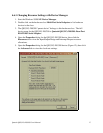
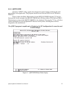
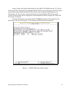
Configuration is usually done using Soft Select, accessable through Device Manager in
Windows operating systems. Hardware overrides are available via jumper J1 for interface signal
routing.
6.1 DTR/DSR or RTS/CTS Operation
The DTR or RTS modem control output of the UART can be used to enable and disable
the transmit drivers. These options are selectable per channel. The factory default, with no
jumpers across any of the pins in J1, is for both the drivers and receivers of both channels to be
continuously enabled. . These option are not selectable via jumpers, they are only accessable
through Device Manager under Window operating systems.
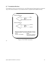
6.2 RTS/CTS Handshake
Transmission of RTS, combined with reception of CTS, allows for hardware handshaking
(data flow control) between the UART and the external device. RTS is transmitted on AUXOUT
and CTS is received on AUXIN by connecting a jumper across the “AUX” pins for the
appropriate port of the jumper block J1. If RTS/CTS handshaking is not desired, the RTS output
can be looped back to the CTS input by removing the any jumper from “AUX” pins for the
appropriate port of the jumper block J1.
6.3 RCLK
This is the clock signal used by the receiver portion of the UART. It is generally provided
by connecting it to the UART's own transmit clock output (TCLK). This signal can only be
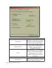
accessed via Soft Select through Device Manager. RCLK is affected by the “Loopback All”,
“Modem Control”, or “Clocks” selections under “RS-422/485 connector set-up” on the
RS-422/485 tab of each port’s property dialog.
6.4 TCLK
This is the output clock signal used by the transmitter portion of the UART. It is generally
connected to the UART's own receive clock input (RCLK). This signal can only be accessed via
Soft Select through Device Manager. TCLK is affected by the “Loopback All”, “Modem
Quatech QSC(LP)-200/300 User's Manual 24