


7 PCI Resource Map
Listed below are the PCI resources used by the QSC(LP)-200/300. Such information may
be of use to customers writing their own device drivers or other custom software. A detailed
description of the QSC(LP)-200/300's UARTs is available on the Quatech web site.
(all numbers in hex)
PCI Vendor ID: 0x135C Quatech, Inc.
PCI Device ID: 0x01A0 QSC(LP)-200/300
PCI Class Code
Base class: 0x07 Simple communications controller
Subclass: 0x02 Multiport serial controller
Interface: 0x00
IRQ sourced by: INTA#
Base Address and Interrupt Level (IRQ)
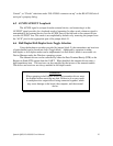
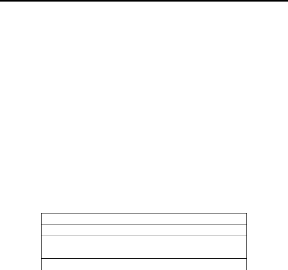
The base address and IRQ used by the QSC(LP)-200/300 are determined by the BIOS or
operating system. Each serial port uses 8 consecutive I/O locations. The four ports reside in a
single block of I/O space in eight-byte increments, along with a sixteen-byte reserved region, for
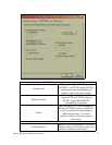
a total of 32 contiguous bytes, as shown in Figure 11.
Base Address + 24 to Base Address + 31Serial 4
Base Address + 16 to Base Address + 23Serial 3
Base Address + 08 to Base Address + 15Serial 2
Base Address + 00 to Base Address + 07Serial 1
I/O Address RangePort
Figure 11. Serial Port I/O addresses
Both serial ports share the same IRQ. The QSC(LP)-200/300 signals a hardware interrupt
when either port requires service. The interrupt signal is maintained until no port requires
service. Interrupts are level-sensitive on the PCI bus.
The base address and IRQ are automatically detected by the device drivers Quatech
supplies for various operating systems. For cases where no device driver is available, such as for
operation under DOS, Quatech supplies the "QTPCI" DOS software utility for manually
determining the resources used. See page 22 for details.
Quatech QSC(LP)-200/300 User's Manual 29