


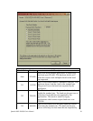
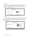
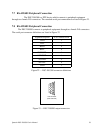
7.2 RCLK
This is the clock signal used by the receiver portion of the UART. It is generally provided
by connecting it to the UART's own transmit clock output (TCLK). This is done by not
connecting pins 1 and 2 of the jumper block J13. If desired, RCLK can be received from an
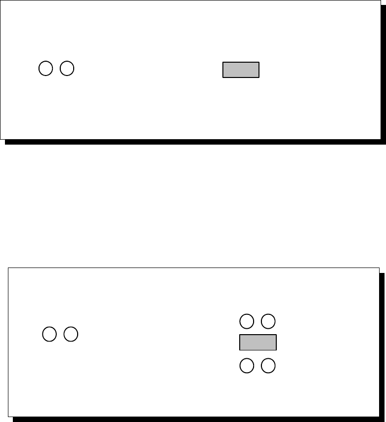
external source over the AUXIN line by connecting pins 1 and 2 of the jumper block J13. Figure
17 shows how to select the RCLK mode.
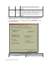
Loopback TCLK to RCLK
Receive RCLK on AUXIN
Jumper J13
RCLK0_SEL
J13
RCLK0_SEL
J13
Figure 17 --- RCLK selection
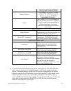
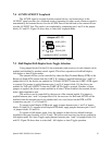
7.3 TCLK
This is the output clock signal used by the transmitter portion of the UART. It is generally
connected to the UART's own receive clock input (RCLK). This is done by not connecting pins 1
and 2 of the jumper block J13. If desired, TCLK can be transmitted to an external source over the
AUXOUT line by connecting pins 1 and 2 of the jumper block J12. Figure 18 shows how to
select the TCLK mode.
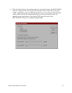
Loopback TCLK to RCLK
Transmit TCLK on AUXOUT
Jumpers J11-13
RCLK0_SEL
J13
RCLK0_SEL
J13
AUX0_SEL0
AUX0_SEL1
J11
J12
Figure 18 --- TCLK selection
Quatech DSC-200/300 User's Manual 34