


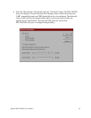
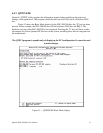
7.4 AUXIN/AUXOUT Loopback
The AUXIN signal is an input from the external device, and connecting it to the
AUXOUT signal provides for a loopback mode of operation. In other words, whatever signal is
transmitted by the external device over the AUXIN line will be fed back to the external device
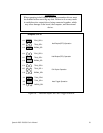
over the AUXOUT line. This mode is accomplished by connecting pins 1 and 2 of the jumper
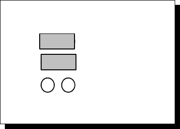
blocks J11 and J12. Figure 19 shows how to select this loopback mode.
Loopback AUXOUT to AUXIN
Jumpers J11-13
RCLK0_SEL
J13
AUX0_SEL0
AUX0_SEL1
J11
J12
Figure 19 --- AUXIN/AUXOUT loopback
7.5 Half-Duplex/Full-Duplex/Auto-Toggle Selection
Using jumper blocks J14 thru J16, the transmitters and receivers of each channel can be
enabled and disabled by modem control signals. This allows operation in both half-duplex,
full-duplex or Auto-Toggle modes.
The transmit drivers can be controlled by either the Data Terminal Ready (DTR) or the
Request to Send (RTS) output from the UART. If a jumper is applied between pins 1 and 2 of
jumper block J14, the drivers are enabled for TxD and AUXOUT when the UART's DTR signal
is asserted. If a jumper is applied between pins 1 and 2 of jumper block J15, the drivers are
enabled for TxD and AUXOUT when the UART's RTS signal is asserted. If neither of these
jumpers is applied, the drivers remain enabled at all times. When disabled, the transmit drivers
enter a high-impedance state.
The receivers can be controlled by the inverse of the transmit enable. If a jumper is
applied between pins 1 and 2 of jumper block J16, the receivers for RxD and AUXIN will be
disabled when the transmit drivers are enabled and vice-versa (based on the DTR or RTS
connections on pins 1-2 of J14 and J15.
To operate in half-duplex DTR mode, apply jumpers between pins 1 and 2 of jumper
blocks J14 and J16. To operate in half-duplex RTS mode, apply jumpers between pins 1 and 2
.of jumper blocks J15 and J16
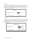
To operate in full-duplex mode, leave the jumpers in their factory default locations,
installed in the spare locations of J14-16 only. The drivers and receivers are always enabled in
full-duplex mode. For Auto-Toggle, apply jumpers between pins 1 and 2 of jumper blocks J14
and J15. Figure 20 shows how to select half-, full-duplex or Auto-Toggle operation.
Quatech DSC-200/300 User's Manual 35