


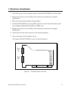

2 Hardware Configuration
The DSC-200/300 is automatically configured at boot time by the computer's BIOS or
operating system. There are no required switches or jumpers to set for installation.
This chapter lists a number of optional
jumper settings that control various hardware
features. These jumpers, located in a column at the end of the board opposite the D-type
connectors, control how signals are routed from the UARTs to the connector, as well as full- or
half- duplex operation and special options.
Any changes from the factory default should be made before installing the DSC-200/300
in the computer.
2.1 Signal Connections
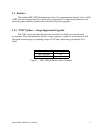
The DSC-200/300 provides each of two serial ports with four differential signal pairs:
TxD, RxD, AUXOUT, and AUXIN. TxD and RxD are always present at the connector. The
AUXOUT and AUXIN signals can be used to support RTS/CTS handshaking, external clocking,
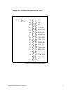
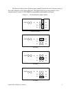
or external signal loopback. The factory default configuration, as shown in Figure 2, is a
loopback of AUXOUT to AUXIN at the connector, with RTS and CTS looped back on the
board. There is an extensive discussion of this topic in section 7.
2.2 Full-duplex/Half-duplex Operation
The DTR or RTS modem control output of the UART can be used to enable and disable
the transmit drivers. The inverse of these signals can also be used to enable and disable the
receivers. These options are selectable per channel. The factory default, as shown in Figure 2, is
for both the drivers and receivers of both channels to be continuously enabled. Spare jumpers are
installed in neutral positions. For details, refer to section 7.5.
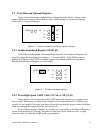
The DSC-200/300 is shipped from the factory with each channel configured with No
jumpers on J10-23. The following conditions occur: CTS=AUXIN, AUXOUT=RTS,
RCLK=TCLK, TXEN=1 AND RXEN=1.
Quatech DSC-200/300 User's Manual 7