


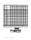
Table 7. Minimum Requirements for E-Series UPS Installation
Term
ID
Description
E61 (E41) E101 (E81) E203 (E153)
Min.
Wire
Gaug
e
(awg)
Term
Torqu
e (in-
lbs)
Min.
Wire
Temp
. (°C)*
Min.
Wire
Gaug
e
(awg)
Term
Torqu
e (in-
lbs)
Min.
Wire
Temp
. (°C)*
Min.
Wire
Gaug
e
(awg)
Term
Torqu
e (in-
lbs)
Min.
Wire
Temp
.
(°C)*
GND
Chassis
Ground
** 40 75 ** 45 75 ** 45 90
L1/N Line 1 8 40 75 6 45 75 4 45 90
L2 Line 2 8 40 75 6 45 75 4 45 90
L3 Line 3 N/A N/A N/A N/A N/A N/A 4 45 90
120A
120 V from
Neutral
10 35 75 6 45 75 4 45 90
0 Neutral 10 35 75 6 45 75 4 45 90
88B
208 V from
120A
10 35 75 6 45 75 4 45 90
120B
120 V from
Neutral
10 35 75 6 45 75 4 45 90
GND
Chassis
Ground
opt 35 75 opt 45 75 opt 45 90
+ +240 VDC to - N/A N/A N/A 4 45 75 4 45 75
-
Battery
Common
N/A N/A N/A 4 45 75 4 45 75
GND
Chassis
Ground
N/A N/A N/A 4 45 75 4 45 75
* Use insulated copper wire rated 75 C minimum.
** Must be no smaller than wire connected to L1/N and L2 (for E61 and E101) or L1, L2, L3 (for E203).
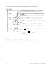
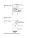
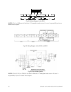
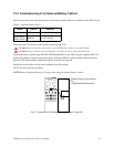
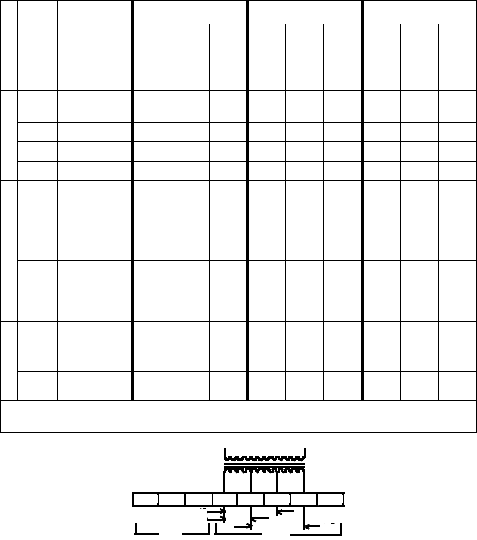
GND L1/N L2 120 0 88B 120 GND
208
120
120
LINE OUT-
X3 X4X2X1
Chloride Active and E-Series UPS User Manual 35
Fig. 23: Wiring Diagram for the E61