


46 Chloride Active and E-Series UPS User Manual
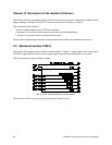
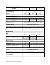
Troubleshooting Optional Interface COM
INV SHUTDOWN
This input (pin 3) is enabled with a high signal (+5 V to +12 V with respect to pin 4 (0 V)) and when enabled,
switches off the UPS after a mains failure has occurred. After the mains has been reestablished, the UPS
starts again independent of this signal status. This input must be high for one (1) second before shut off will
occur.
AC FAIL
This output provides an N/O (Normally Open) contact between pins 9 and 5, and an N/C (Normally Closed)
contact between pins 8 and 5. the 9-5 contact closes when the mains voltage fails at the UPS input or when
the mains voltage falls below the lower limit for a minimum of 10 seconds. This contact opens
approximately 850 ms after the mains have been reestablished. The 8-5 contact provides a mirror function,
opening when the mains voltage fails and closing when mains power returns.
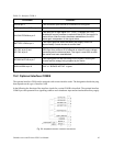
LOW BATT
This output provides a N/O contact between pins 6 and 5 and an N/C contact between pins 7 and 5. The 6-
5 contact closes when the battery has been depleted to the point that it can only supply current for
approximately three (3) more minutes at nominal load. The 7-5 contact provides a mirror function opening
when the battery is low.
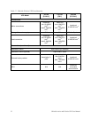
BYPASS ACTIVE
This output provides an N/O contact between pins 1 and 5. The 1-5 contact closes after switching to the
bypass mode. In the bypass mode, energy to the output of the UPS is being supplied by the mains power and
not through the inverter.
SUM ALARM
This output provides an N/O contact between pins 2 and 5. The 2-5 contact closes when one of the alarms
“AC FAIL,” “LOW BATT” or “BYPASS ACTIVE” is active or when the indication “ALARM” at the front-
panel is on.
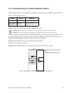
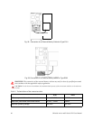
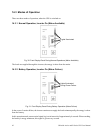
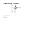
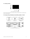
15.3 Emergency Power Off (EPO)
(E-Series Models E153X and E203X only)
The external connection to the EPO circuit is located next to the 9-pin SUB-D (interface com A) connector
in the upper right of the back of the unit. If the circuit between the two EPO connector pins is “opened,” the
output of the UPS is immediately switched off. To restart the UPS, the procedures outlined in
section 13.3
on page 37 must be followed. The EPO circuit may be extended by connecting normally closed switches in
series between the EPO connector pins. Activating (opening) any of the series switches will cause the UPS
to shut off its output.