


GND L1/N L2 120 0 88B 120 GND
208
120
120
LINE OUT-
+ -
GND
BAT-
X3 X4X2X1
36 Chloride Active and E-Series UPS User Manual
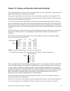
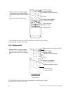
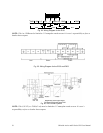
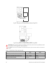
Fig. 24: Wiring Diagram for the E101
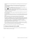
NOTE: 120 A or 120B must be limited to 1/2 nameplate rated current. It is user’s responsibility to fuse or
breaker these outputs.
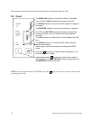
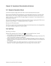
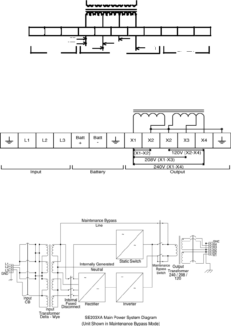
Fig. 25: Wiring Diagram for the E153 and E203
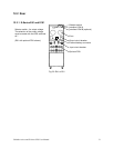
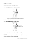
Fig. 26: E203 Power System
NOTE: 120 A (X1-X2) or 120B (x2-x4) must be limited to 1/2 nameplate rated current. It is user’s
responsibility to fuse or breaker these outputs.