


Chapter 3 Operation FCD-IPM Installation and Operation Manual
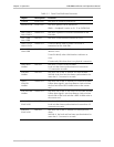
3-2 Indicators
Table 3-1. Front Panel Indicator Functions
Object Description Function
POWER Green LED ON when FCD-IPM is powered on.
READY/LOOP Green LED ON when packets can be transferred.
Blinks – a loopback is active on E1, T1 or SHDSL link
LAN 1 DATA
LAN 2 DATA
Yellow LED ON when a packet is received or transmitted on the
LAN side.
LAN 1 ERR
LAN 2 ERR
Red LED ON when a LAN interface indicates an error.
LINK 1 DATA
LINK 2 DATA
Yellow LED Turns ON briefly when a packet is received or
transmitted on the LINK side.
LINK1 ERR
LINK2 ERR
Red LED OFF when there is a physical connection and no LINK
interface error.
Turns ON briefly when LINK interface indicates an
error.
Continuously ON when there is no physical connection.
LINK1 RED
ALARM
Red LED ON when T1 link is in RED ALARM.
Local unit lost frame synchronization for more than
2.5 consecutive seconds.
SUB RED
ALARM
Red LED ON when one of the T1 sub link is in RED ALARM.
Sub link of the local unit lost frame synchronization for
more than 2.5 consecutive seconds.
LINK1
YELLOW
ALARM
Yellow LED ON when one of the T1 sub link is in YELLOW ALARM.
Yellow alarm signal is sent from Remote Unit to inform
the local unit that a RED ALARM exists at the remote
end.
SUB YELLOW
ALARM
Yellow LED ON when one of the T1 sub link is in YELLOW ALARM.
Yellow alarm signal is sent from Remote Unit to inform
the sub link of the local unit that a RED ALARM exists at
the remote end.
LINK1 LOC
SYNC LOSS
Red LED ON when E1 link is in local sync loss alarm.
Local unit lost frame synchronization for more than 2.5
consecutive seconds.
SUB LOC
SYNC LOSS
Red LED ON when one of the E1 sub link is in local sync loss
alarm.
Sub link of the local unit lost frame synchronization for
more than 2.5 consecutive seconds.