12
11.3.0
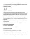
Hardware Setup
11.3.1.1 1500 Interface Card Setup
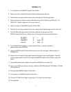
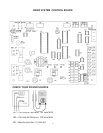
11.3.1.1 Connecting Power to the T-3 Card
The T-3 Card requires an external source of DC voltage. The
DC source voltage should be between 9V and 30V. The power is
connected to TB1, located near the two 9 pin serial port connec-
tions.
The connection to TB1 is as follows:
TB1-1 9-30 VDC (+)
TB1-2 Common (-)
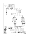
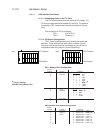
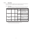
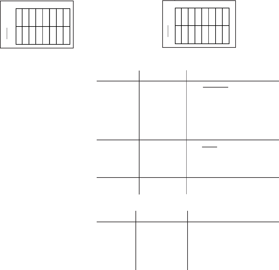
11.3.1.2 Dip Switch Configuration
The T-3 card is configured primarily through two sets of dip
switches. These switches are read initially on power up only.
The function of the dip switches is as follows (a value of one (1)
is registered when the a switch is in the ON position):
OFF Position: OFF Position:
ON Position: ON Position:
SW1 : Modbus Port Configuration
Switch
Position Function Positions
1 Baud Rate 3 2 1
2 Selection 000300
3 001600
0 1 0 1200
0 1 1 2400
1 0 0 4800
1019600 -
1 1 0 19200
1 1 1 19200
4 Parity 5 4
5 Selection 0 0 None -
0 1 Odd
1 0 Even
1 1 Invalid
6 Not Used
7
8
SW2 : Modbus Slave Address Configuration
Switch
Position Function Positions
1 Baud Rate 1 Address Bit 0 Value = 1
2 Address 2 Address Bit 1 Value = 2 -
3 Select 3 Address Bit 2 Value = 4
4 4 Address Bit 3 Value = 8
5 5 Address Bit 4 Value = 16
6 6 Address Bit 5 Value = 32
7 7 Address Bit 6 Value = 64
8 8 Address Bit 7 Value = 128
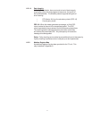
Factory Settings
9600, No Parity, Address Bit 1
*
*
*
*
O
F
F
12345678
• ••••••
•
12345678
• •••••
••
O
F
F
↓
↓
SW 1
SW 2


