


M306NKT-EPB User’s Manual 3. Usage (How to Use the Emulator Debugger)
REJ10J0519-0200 Rev.2.00 Oct. 16, 2006 Page 70 of 104
3.6 RAM Monitor Window
This function makes it possible to make reference to the changes in memory contents without impairing the real-time
performance for target program execution. The emulator PC7501 system is provided with the 4KB RAM monitor area. This
RAM monitor area can be divided into the 16-block area in units of arbitrary continuous address or 256 bytes for mapping or
layout.
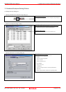
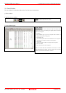
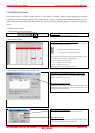
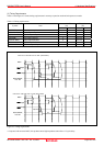
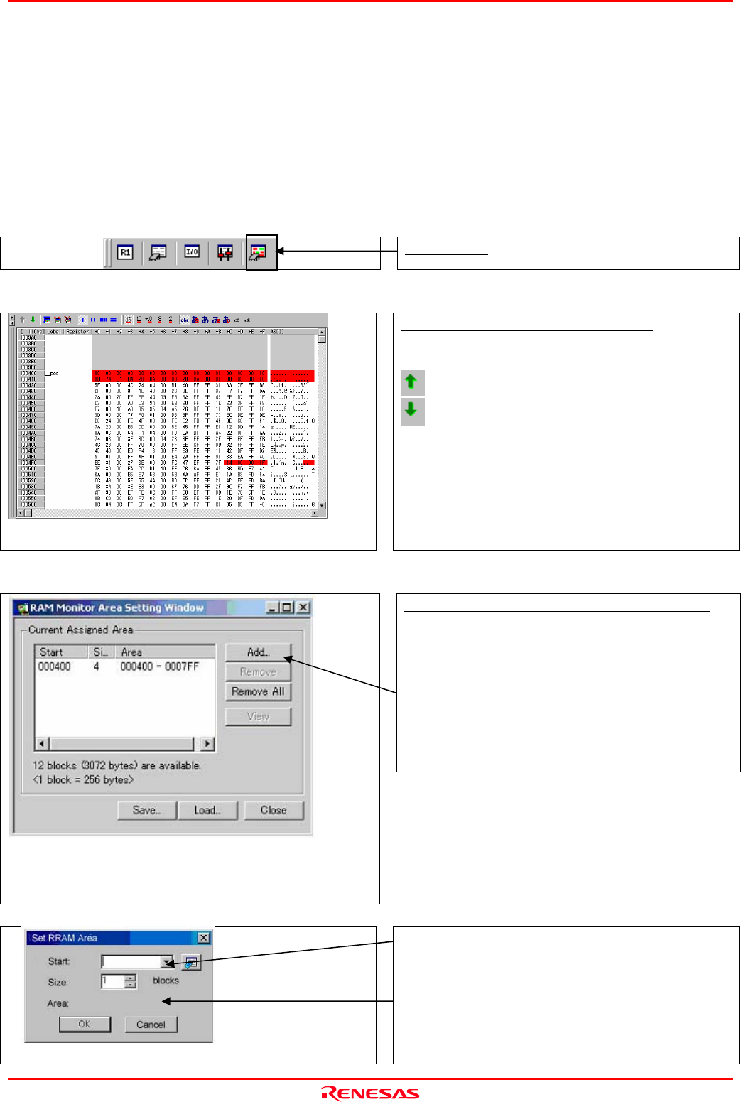
(1) RAM monitor window
1. Opening the trace point setup window
RAM monitor
Clicking this button opens the RAM monitor window.
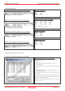
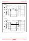
2. RAM monitor display
Changing the RAM monitor display area
You can change the manner in which the RAM monitor area you have
set in the above dialog box is displayed.
: Shows the blocks at the preceding addresses.
: Shows the blocks at the following addresses.
The background colors of the data display and the code display sections
change with the access attribute as described below.
- Green : Addresses accessed for read
- Red : Addresses accessed for write
- White : Addresses not accessed
The background colors can be changed as necessary.
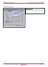
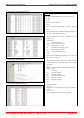
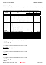
3. RAM monitor area setting window in initial state
RAM Monitor Area Setting Window in initial state
By default, the monitor area is set to 000400h through 0007FFh. To
change it, click the line you want to set.
Specifying the start address
You can set the start address of the RAM area to be monitored. To add
a RAM monitor area, click the "Add..." button. The RAM Monitor Area
Setting dialog box will be displayed.
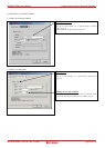
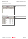
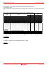
4. RAM monitor area setting dialog box
Specifying the start address
You can set the start address of the RAM area to be monitored.
Specifying the size
You can set the size to be monitored by specifying the number of blocks
from the start address. One block is 256 bytes in size.