


M306NKT3-RPD-E User’s Manual 2. Setup
REJ10J0326-0400 Rev.4.00 Sep. 01, 2006 Page 40 of 104
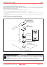
2.9.2 Each Setting
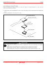
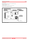
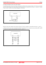
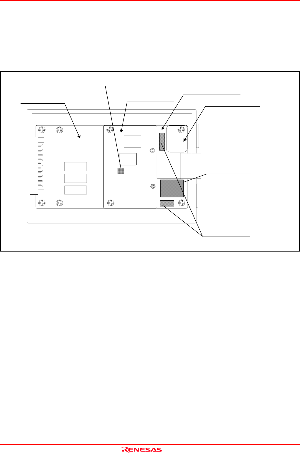
Figure 2.18 shows the positions of each part of the M306NKT3-RPD-E.
(1) Position of oscillator circuit board
(2) Position of switches
(3) Position of socket for mounting network resister for pullup
(4) Position of bypass capacitor for A/D converter
Figure 2.18 Positions of each part
MCU dependent board 2
(M3062PT3-PRTM)
Common board
(M30620T3-RPDC)
(3) Socket for
mounting network
resister for pullup
(2) Switches
(1) Oscillator circuit board
(4) Bypass capacitor for A/D converter
MCU dependent board 1
(M30620T3-PRT)