


M306NKT3-RPD-E User’s Manual 2. Setup
REJ10J0326-0400 Rev.4.00 Sep. 01, 2006 Page 45 of 104
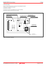
2.9.4 Switch Settings
Here follows explanations of the switches of the emulation pod. Set the switches according to the user system.
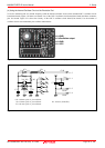
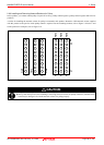
Tables 2.3 and 2.4 list how to set toggle switches SW1 to SW5 of the M30620T3-PRT board (MCU-dependent board 1). Table
2.5 lists how to set jumper switches JP1 and JP2. For the positions of the switches, see Figure 2.18.
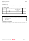
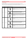
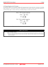
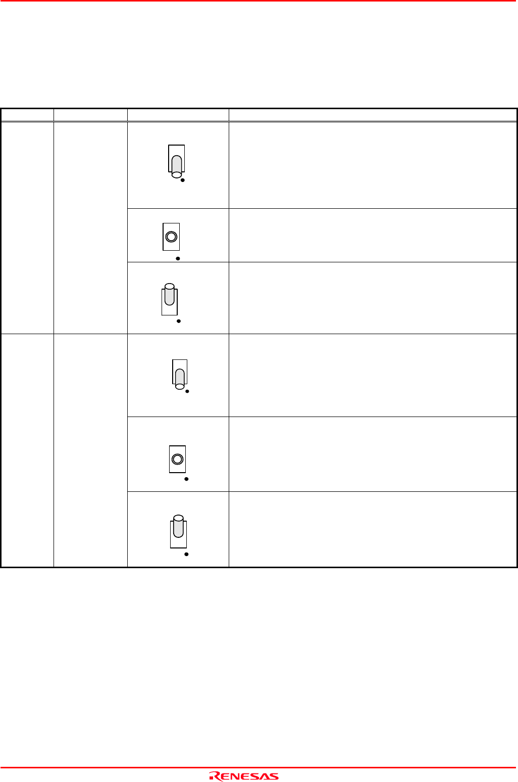
Table 2.3 Switch settings of the M306NKT3-RPD-E (1)
Signal Switch Setting Description
BYTE
HOPEN
(factory-settings)
L
SW1
Sets pin BYTE of the MCU to "L" when the user system is
unconnected.
Pulls down pin BYTE of the MCU with a resistance of 33kΩ.
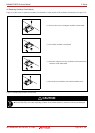
BYTE
H
OPEN
L
SW1
Use this setting when the user system is connected.
Does not pull up/down pin BYTE of the MCU.
(Inputs the level of the user system to pin BYTE of the MCU.)
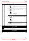
BYTE SW1
BYTE
H
OPEN
L
SW1
Sets pin BYTE of the MCU to "H" when the user system is
unconnected.
Pulls up pin BYTE of the MCU with a resistance of 33kΩ.
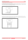
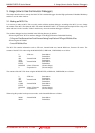
CNVss
H
OPEN
L
SW2
(factory-settings)
Sets pin CNVss of the MCU to "L" when the user system is
unconnected.
Pulls down pin CNVss of the MCU with a resistance of 1kΩ.
CNVss
H
OPEN
L
SW2
Use this setting when the user system is connected.
Does not pull up/down pin CNVss of the MCU.
(Inputs the level of the user system to pin CNVss of the MCU.)
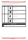
CNVss SW2
CNVss
H
OPEN
L
SW2
Sets pin CNVss of the MCU to "H" when the user system is
unconnected.
Pulls up pin CNVss of the MCU with a resistance of 1kΩ.