


( 20 / 54 )
Chapter 3. Setting Up
With this product, it is necessary to set switches of the emulation pod and connect the RESET, GND
and Vcc cables according to your target system.
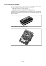
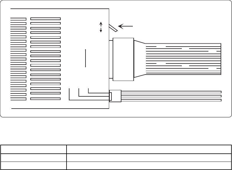
3.1 Switch Settings
The M38000TL2-FPD is designed for use with the RSS/RFS and RLSS/RLFS chips*
1
in the 740
Family MCUs.
The MCU type select switch (SW1) is used to switch the emulator MCU's operating supply voltage
sense input and feeding supply voltage output via Vcc cable. You need to set up the MCU type select
switch and modify the connection of Vcc cable depending on the type of your emulator MCU.
*1 RLSS/RLFS represent the names of emulator MCUs that can operate with a supply voltage of less
than 2.0 V.
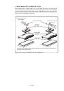
(1) When the type of the emulator MCU is M3xxxxRLSS or M3xxxxRLFS:
Set SW1 to the RLSS side and connect the Vcc cable to the Vcc on the target system.
(2) When the type of the emulator MCU is M3xxxxRSS or M3xxxxRFS:
Set SW1 to the RSS side and do not connect Vcc cable.
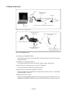
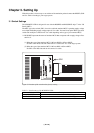
Figure 3.1 Position of the switch and its factory-setting
Table 3.1 Switch setting of the M38000TL2-FPD
BLACK: GND
BLACK: GND
YELLOW: VCC (SENSE)
YELLOW: VCC (SENSE)
TARGET
TARGET
RSS
RLSS
RLFS
SW1
WHITE: RESET
WHITE: RESET
RFS
Setting Description
RSS/RFS side When the emulator MCU is RSS/RFS type
RLSS/RLFS side When the emulator MCU is RLSS/RLFS type