


( 29 / 54 )
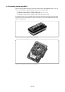
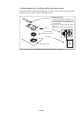
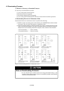
(3) Connecting the M38000TL2-PSW to the Target System
Connect the clips for RESET, GND and Vcc on the tip of the M38000TL2-FPD's three-color cables
to the RESET, GND and Vcc pins on the target system.
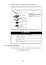
(1) Reset cable (white)
(2) GND cable (black)
(3) Vcc cable (yellow)
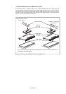
These three types of cables are connected differently depending on how the MCU type select switch
(SW1) is set. Table 3.2 lists the SW1 settings and the connection of the RESET, GND and Vcc cables.
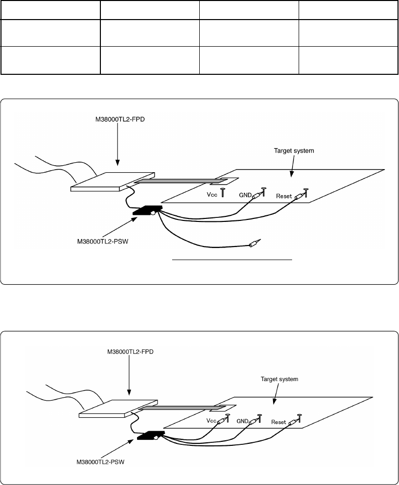
Figures 3.11 and 3.12 show how to connect the cables.
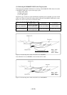
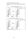
Table 3.2 Connecting RESET, GND and Vcc cables
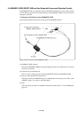
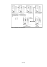
Figure 3.11 Connecting three cables when SW1 is set to RSS/RFS
Note: When SW1 is set to RSS/RFS, do not connect the Vcc cable.
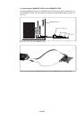
Figure 3.12 Connecting three cables when SW1 is set to RLSS/RLFS
SW1 set to RSS/RFS
RESET (white)
Connect to the RESET
pin on the target system.
Connect to the RESET
pin on the target system.
GND (black) Vcc (yellow)
SW1 set to RLSS/RLFS
Connect to the GND pin. Not connected
Connect to the GND pin. Connect to the Vcc pin.
Black: GND
Yellow: Vcc
White: RESET
Black: GND
Yellow: Vcc
White: RESET
Do not connect the Vcc cable.