


( 30 / 54 )
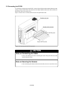
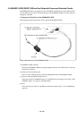
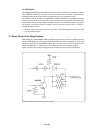
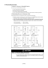
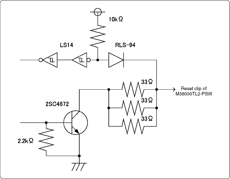
Figure 3.13 Connection diagram of reset circuit
(4) LED Display
The M38000TL2-PSW turns off the LED to alert you when Vcc and GND are mistakenly connected.
The M38000TL2-PSW may become hot when Vcc and GND are mistakenly connected. If so,
immediately turn off the power and check whether these pins are connected correctly.
The LED does not go out when Vcc and RESET or GND and RESET are mistakenly connected.
However, because in this case the emulator system cannot be started, immediately turn off the power
to the emulator and target system and check whether these pins are connected correctly. Also, because
the emulator system may probably be unable to start for some other reasons, refer to "Chapter 6.
Troubleshooting" (page 41).
* When the voltage of the target system is lower than 3.3 V, the LED lights darkly or does not light
even in normal operation.
3.7 Reset Circuit of the Target System
When debugging with M38000TL2-FPD, use either an open-drain type reset IC or a CR reset circuit.
The recommended pull-up value is about 10kΩ. The MCU can be reset by outputting "L" to the target
through the reset clip on the M38000TL2-FPD. However, if the reset circuit on the target is an H-
output type RESET IC, it cannot be set to "L" and the emulator will not operate properly.
Figure 3.13 shows the connection diagram of the internal reset circuit of the emulation pod.