


5
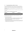
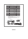
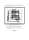
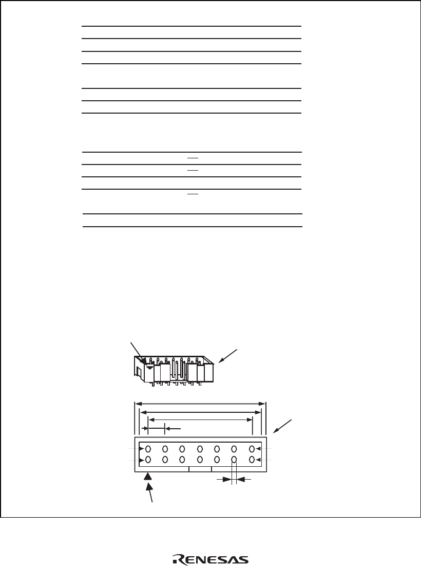
Pin 1 mark
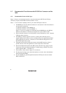
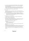
Notes:
1. Input to or output from the user system.
2. The symbol (/) means that the signal is active-low.
3. The emulator monitors the GND signal of the user
system and detects whether or not the user system
is connected.
25.0
23.0
6 x 2.54 = 15.24
(2.54)
0.45
Pin 1
Pin 8
Pin 7
Pin 14
Pin 1 mark
H-UDI port connector
(top view)
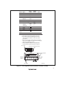
H-UDI port connector
(top view)
Pin No. Signal
1
2
3
4
5
6
7
8
9
11
10, 12,
and 13
14
TCK
/TRST
TDO
/ASEBRK /
BRKACK
TMS
TDI
/RESETP
/RESETA
/RESETMFI
N.C.
(GND)
UVCC
GND
Input/
Output*
1
*2
*2
GND
*3
Output
Input
Input
Output
Input/
output
Input
Input
Output
Output
Output
Output
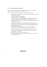
4.
When the user system interface cable is connected to
this pin and the MPMD pin is set to 0, do not connect to
GND but to the MPMD pin directly.
5.
Connect /RESETP, /RESETA, and /RESETMFI to
the user system if required, as shown in figure 1.4.
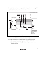
Note
User reset
*2
*5
*4
SH7343
Pin No.
AB15
W14
Y14
AA13
W15
V15
V16
AB17
E11
Unit: mm
Figure 1.2 Pin Assignments of the H-UDI Port Connector (14 Pins)