


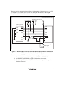

13
8. Cache Operation during User Program Break
When cache is enabled, the emulator accesses the memory by the following methods:
• At memory write: Writes through the cache, then issues a single write to outside. The LRU
is not updated.
• At memory read: Reads memory from the cache. The LRU is not updated.
Therefore, when memory read or write is performed during user program break, the cache state
does not change.
• At breakpoint set: Disables the instruction cache.
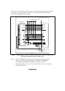
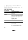
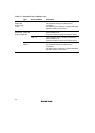
9. Port G
The AUD pin is multiplexed as shown in table 2.2.
Table 2.2 Multiplexed Functions
Port Function 1 Function 2
G PTG4 input/output (port)* AUDSYNC (AUD)
G PTG3 input/output (port)* AUDATA3 (AUD)
G PTG2 input/output (port)* AUDATA2 (AUD)
G PTG1 input/output (port)* AUDATA1 (AUD)
G PTG0 input/output (port)* AUDATA0 (AUD)
Note: Function 1 can be used when the AUD pins of the device are not connected to the emulator.
10. UBC
When [User] is specified in the [UBC mode] list box in the [Configuration] dialog box, the
UBC can be used in the user program.
Do not use the UBC in the user program as it is used by the emulator when [EML] is specified
in the [UBC mode] list box in the [Configuration] dialog box.
11. MFI
When the MFI boot mode is used, be sure to activate the emulator by setting the MFIINT
signal as a trigger for the MFI transfer from the base-band side.
In the active-through mode, the emulator does not operate during break.