


RF Neulink
NL6000 User Guide
13
4. Hardware Installation and Operation
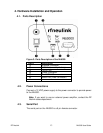
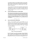
4.1. Parts Description
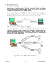
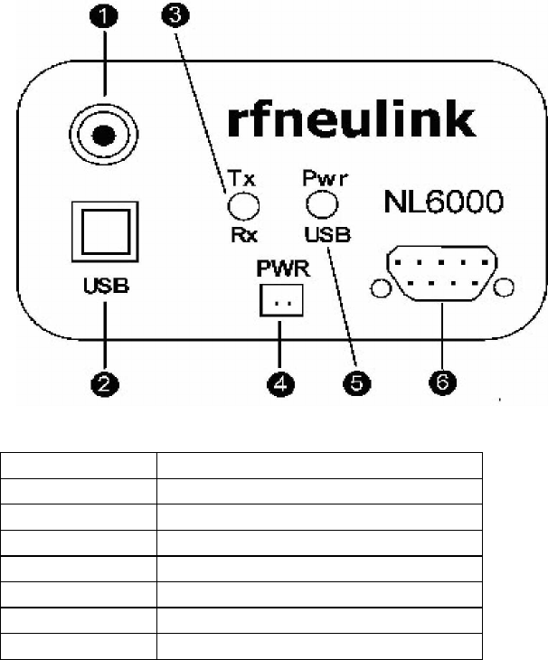
Figure 3: Parts Description of the NL6000
Part # Description
(1) Antenna Connector
(2) USB Port (used by factory)
(3) Tx/Rx LED
(4) Power Connector
(5) Pwr/USB LED
(6) Serial Port (DB9 Connector
)
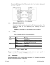
4.2. Power Connections
Connect a 12 VDC power supply to the power connector to provide power
to the NL6000.
Note:
If you want to use an external power amplifier, contact the RF
Neulink sales department.
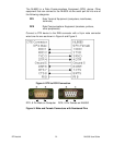
4.3. Serial Port
The serial port on the NL6000 is a 9 pin female connector.