


RF Neulink
NL6000 User Guide
46
•
Enter the active channel assignment for the radio. The value must
be a number in the range 01 64.
•
Press
ESC
to return to the
Main Menu
.
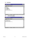
4. Select
Diagnostics
ä
Transmit Continuous Random Data
.
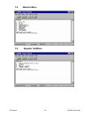
5. Set the power value as follows:
•
Select
Power
from the
Diagnostics
menu.
•
While watching the power gauge, change the power value and
check the gauge to see that the power value registers correctly. The
value must be a number in the range 0 1023.
•
Press
ESC
to return to the
Diagnostics
menu.
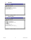
6. Set the frequency trim as follows:
•
Select
Frequency Trim
from the
Diagnostics
menu.
•
While watching the Frequency Error gauge on the IFR, change the
frequency trim value on the
Frequency Trim
window until the
needle on the gauge is centered.
7. Select
None
from the
Diagnostics
menu to stop the data transmission
Setting the Deviation and Balance
To properly set the deviation and balance, you must perform the following
procedure twice once near each edge of the transmit frequency band.
In this procedure, an edge is defined as approximately 2.5 MHz from one
end of the band range.
1. From the terminal emulator, enter programming mode.
2. Select one edge of the transmit frequency as follows:
•
Select
Radio
Ä
Transmit Frequency for Active Channel
.
•
Enter a frequency that is on one edge of the frequency for
the active radio channel. The value must be a number in the
format
nnn.nnnn
.
•
Press
ESC
to return to the
Main Menu
.
3. Set the IFR to receive at the transmit frequency you set in Step 2.
4. Select
Diagnostics
ä
Transmit 100 Hz Square Wave
.
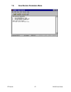
5. Set the balance value as follows:
•
Select
Balance
from the
Diagnostics
menu.
•
While watching the square wave on the IFR, enter
1-Increase
Balance 0.125 dB
or
2-Decrease Balance 0.125 dB
until the
corners of the wave are at a 90 angle.
•
Press
ESC
to return to the
Diagnostics
menu.
6. Select
None
from the
Diagnostics
menu to stop the square wave.
7. Select
Transmit Continuous Random Data
from the
Diagnostics
menu.