


5
4 BASIC OPERATION
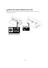
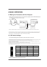
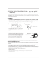
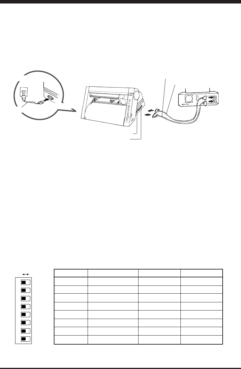
4-1 Making the Connection with the Computer
* Always make sure that the power is off on both the computer and the PNC-900 whenever
any cables are connected or disconnected.
Serial interface cable
Cables are available separately. One which you are sure matches the model of computer being used should be selected.
When the PNC-900 is connected to the computer via the serial port, the communication parameters for the PNC-900 need to
be set at the same values as for the computer. Use the DIP switches on the right-hand side of the PNC-900 to make these
settings. Refer to "4-2 DIP Switch Settings" on page 5 to make the correct settings.
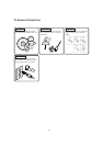
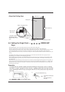
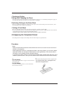
4-2 DIP Switch Settings
* DIP switches settings must be made only when the power is turned off.
The DIP switches are located on the right-hand side of the unit. The settings that can be made with these DIP switches are the
communication parameters for when the serial port is used, and the value for the blade offset.
When the PNC-900 and the computer are connected through the serial port, use SW-1 through SW-6 to make the correct
settings for communication parameters.
The blade offset, which is set with SW-7, should normally be set to OFF (0.25 mm).
The setting for sheet weight, made with SW-8, should normally be set to OFF (light). See "Cutting a Thick Sheet" on page 11
for an explanation of the settings for SW-8.
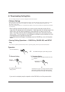
Serial connector
or
parallel connector
Parallel interface cable
Parallel input connector
Serial input connector
Power connector
Power cord
Power outlet
8
76
5
4
32
1
OFF ON
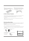
DIP switch Function OFF ON
SW-1 Baud rate 9600 4800
SW-2 Parity check Disable Enable
SW-3 Parity check ODD EVEN
SW-4 Data bits 8-bit 7-bit
SW-5 Stop bits 1-bit 2-bit
SW-6 Handshake Hardwire XON/XOFF
SW-7 Blade offset 0.25 0.5*
SW-8 Sheet weight Light Heavy
*Option required ; please consult your dealer.
• All DIP switches are set to OFF when shipped from the factory.
• When SW-2 is set to OFF, SW-3 may be set to either ON or OFF.