


18
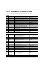
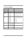
8 LIST OF CAMM-GL III INSTRUCTIONS
*1: -(2
26
-1) — +(2
26
-1) *2: 0 — +(2
26
-1) *3: -(2
26
-1)° — +(2
26
-1)° *4: 21
(16)
— 3A
(16)
, 3C
(16)
— 7E
(16)
• mode1
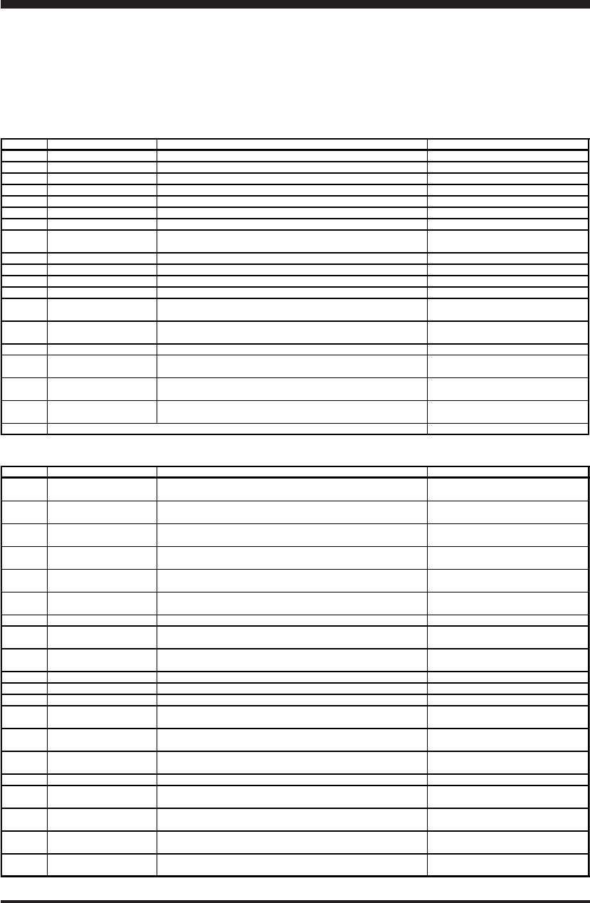
Instruction Format Meaning of Parameter [Parameter Range (Default)] Explanation
H H None Move to User Origin
D D x1, y1..., xn, yn xn: Absolute X-axis coordinate [*1] yn: Absolute Y-axis coordinate [*1] Cut Absolute Line
M M x1, y1...xn,yn xn: Absolute X-axis coordinate [*1] yn: Absolute Y-axis coordinate [*1] Tool-up to Absolute Coordinate Point
II ∆x1, ∆y1...,∆xn, ∆yn ∆xn: Relative X-axis coordinate [*1] ∆yn: Relative Y-axis coordinate [*1] Cut Relative Line
RR ∆x, ∆y ∆xn: Relative X-axis coordinate [*1] ∆yn: Relative Y-axis coordinate [*1] Tool-up Move to Relative Coordinate Point
L L p p: Line pattern [-5 — +5(0)] Specify Line Type
B B l l: Pitch length [*2 1.5% of (P2-P1) ] Specify Broke Line Pitch
X X p,q,r p: Coordinate axis [0, 1] q: Tick interval [*1] Plot Coordinate System
r: Number [1—32767]
P P c1c2...cn cn: Character Plot Character
S S n n: Character size [0 — 127(61)] Set Character Size
Q Q n n: Rotation angle (90°as a unit) [n =0 — 3(0)] Specify Character Rotate Angle
N N n n: Number of special symbol [1—15] Plot Special Symbol
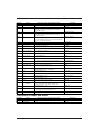
C C x, y, r, Ø1, Ø2(,Ød) x, y: Center coordinates [*1] r: Radius [*1] Cut Arc
Ø1•Ø2: Start angle • End angle [*1] Ød: Chord tolerance [*1 (5°)]
E E r, Ø1, Ø2(,Ød) r: Radius [*1] Cut Arc from Tool Position
Ø1•Ø2: Start angle • End angle [*1] Ød: Chord tolerance [*1 (5°)]
A A x, y x: Center x coordinate [*1(0)] y: Center y coordinate [*1(0)] Specify G & K Center Coordinate
G G r,Ø1, Ø2(,Ød) r: Radius [*1] Ø1: Start angle [*1] Ø2: End angle [*1] Cut Arc Around A-Instruction Center
∆d: Chord tolerance [*1 (5°)]
K K n, l1, l2 n: Division line angle [*1] l1: Division line end point distance [*1] Plot Division Line
l2: Division line start point distance [*1]
T T n, x, y, d, t n: Hatching pattern [0 — 3] x, y: Rectangle size [*1] Plot and Hatch Rectangle
d: Hatching spacing [*1] t: Hatching angle [1 — 4]
^ [mode 2 instruction] [parameter]....., [parameter] [terminator] Call mode 2
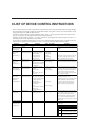
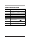
• mode2
Instruction Format Meaning of Parameter [Parameter Range (Default)] Explanation
AA AA x,y,Øc(,Ød); x, y: Absolute center coordinates [*1] Arc Absolute
Øc:Center angle [*1] Ød: Chord tolerance [*1 (5°)]
AR AR ∆x, ∆y,Øc(,Ød); ∆x, ∆y: Relative center coordinates [*1] Arc Relative
Øc: Center angle [*1] Ød: Chord tolerance [*1 (5°)]
CA CA n; n: Character set No. [0 — 4, 6 — 9, 30 — 39 Alternate Character set
CA;
CI CI r(,Ød); r: Radius [*1] Circle
Ød: Chord tolerance [*3 (5°)]
CP CP nx,ny; nx: Number of characters in X-axis direction [*1] Character Plot
CP; ny: Number of characters in Y-axis direction [*1]
CS CS n; n: Character set number Standard Character Set
CS;
DF DF; None Default
DI DI run, rise; run: X-axis direction vector [*1 (1)] Absolute Direction
DI; rise: Y-axis direction vector [*1 (0)]
DR DR run, rise; run: X-axis direction vector [*1 (1)] Relative Direction
DR; rise: Y-axis direction vector [*1 (0)]
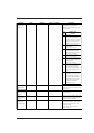
DT DT t; t: Label terminator [ [ETX] ] Define Label Terminator
EA EA x, y; x, y: Absolute XY coordinates of opposite angle of rectangle [*1] Edge Rectangle Absolute
ER ER ∆x, ∆y; ∆x, ∆y: Relative XY coordinates of opposite angle of rectangle [*1] Edge Rectangle Relative
EW EW r, Ø1, Øc(,Ød); r: Radius [*1] Ø1: Start angle [*3] Edge Wedge
Øc: Center angle [*3] Ød: Chord tolerance [*3 (5°)]
FT FT n(,d(,Ø)); n: Pattern [1 — 5 (1)] Fill Type
FT; d: Spacing [*2 ((P2x-P1x) x 0.01)] Ø: Angle [*3 (0°)]
IM IM e; e: Error mask value [0 — 255 (223)] Input Mask
IM;
IN IN; None Initialize
IP IP P1x, P1y, P2x, P2y; P1x, P1y: XY coordinates of P1 [*1] Input P1 & P2
IP; P2x, P2y: XY coordinates of P2 [*1]
IW IW LLx, LLy, URx, URy; LLx, LLy : lower left coordinates of window Input Window
IW; URx,URy : Upper right coordinates of window
LB LB c1c2c3...cn c: Character string Label
[label terminator]
LT LT n(,l); n: Pattern number [0 — 6 (solid line)] Line Type
LT; l: 1 pitch length [*2 (1.5% of (P2-P1))]