


Runco VX-2ix Owner’s Operating Manual xi
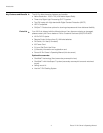
1List of Figures
2-1. VX-2ix Front/Bottom/Side View ....................................................................................5
2-2. VX-2ix Rear Panel.........................................................................................................6
2-3. VX-2ix Remote Control.................................................................................................9
3-1. Estimating Throw Distance.........................................................................................16
3-2. Projector Placement...................................................................................................17
3-3. Vertical Lens Shift (Example Only)...............................................................................18
3-4. Horizontal Lens Shift (Example Only)...........................................................................18
3-5. Folded Optics.............................................................................................................19
3-6. DVI Source Connections ............................................................................................21
3-7. Digital (DTV) RGB Connections...................................................................................22
3-8. Analog RGB Connections...........................................................................................23
3-9. Composite, S-Video and Component Video Connections...........................................24
3-10. RS-232 Control System Connection.........................................................................25
3-11. Connecting the 12-Volt Trigger Output to the AutoScope Lens Motor......................25
3-12. Connecting a 12-Volt Trigger Output to Other Equipment.........................................26
4-1. VX-2ix OSD Menu Structure .......................................................................................29
4-2. Typical PLUGE Pattern for Adjusting Brightness .........................................................33
4-3. Typical Gray Bar Pattern for Adjusting Contrast..........................................................34
4-4. Typical Color Bar Pattern for Adjusting Color Saturation and Tint................................35
4-5. Typical Test Pattern for Adjusting Sharpness..............................................................36
7-1. VX-2ix Dimensions .....................................................................................................60
A-1. CIE 1931 Chromaticity Diagram ............................................................................... A-1
A-2. Equipment Setup for Color Gamut Adjustment......................................................... A-2
A-3. VX-2ix Secondary RS-232 Port ................................................................................ A-3