


INSTALLATION
Spinpoint
M8 Product Manual REV
2.3
16
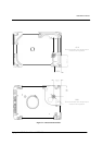
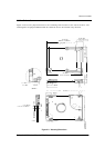
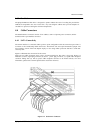
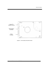
4.3.2 Clearance
The printed circuit board (PCB) is designed to be very close to the mounting holes. Do not exceed the
specified length for the mounting screw described in Figure 4-3. The specified screw length allows full use of
the mounting-hole threads, while avoiding damage or placing unwanted stress on the PCB.
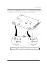
Figure 4-3: Mounting-Screw Clearance
CAUTION: Using mounting screws that are longer than the maximum
lengths specified in Figure 4-3 voids the warranty of the drive.