


INSTALLATION
Spinpoint
M8 Product Manual REV
2.3
19
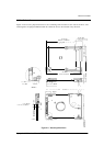
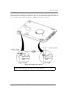
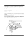
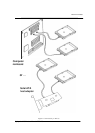
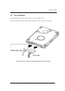
Figure 4-5 illustrates Connectivity of SATA to drives. It can be used with a SATA host bus adapter (lower
picture) or directly into motherboard that has the SATA built-in host bus adapter (upper picture).
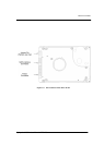
SATA Device Connector Definition
Please note that all pins are in a single row, with a 1.27 mm (50 mil) pitch diameter. There are three
power pins for each voltage source. One pin from each voltage is utilized for pre-charge when installed in
a blind- mate backplane configuration.
The notes on the mating sequence apply to the case of backplane blind mate connector.
When the drive is inserted, the ground pins and the pre-charge pins are in contact first followed by the
remaining pins.
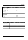
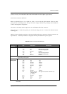
Table 4-1 lists the signals connection on the SATA interface and power connector. It is based on SATA 1.0a
Specifications. Note that pin numbers is designated from the pin farthest from power segment.
Table 4-1 SATA Connector Pin
Definitions
Data Signal
Connector
Pin Function Definition
*S1 Ground Ground
S2 Rx+ Differential Signal pair
S3 Rx- Differential Signal pair
*S4 Ground Ground
S5 Tx- Differential Signal Pair
S6 Tx+ Differential Signal pair
*S7 Ground Ground
Key and spacing separate
signal and power segment
Power
Management
P1 V
33
3.3
v
P2 V33 3.3
v
*P3 V
33 3.3 v
*P4 Ground Ground
*P5 Ground Ground
*P6 Ground Ground
*P7 V
5 5 v
P8 V
5 5 v
P9 V
5 5 v
*P
10 Ground Ground
P
11 Device Activity This pin was reserved in SATA 1.0a
/ Stagger Spin-
up Control
*P
12 Ground Ground
*P
13 V12 12 v
P
14 V12 12 v
P
15 V12 12 v
* First Mate