


--- ---
--- ---
--- ---
--- ---
--- ---
--- ---
Interface Description SanDisk CompactFlash Card OEM Product Manual
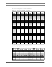
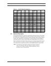
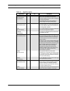
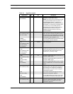
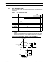
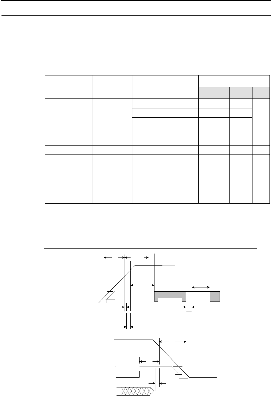
3.3.3 Power Up/Power Down Timing
The timing specification in Table 3-9 was defined to permit peripheral cards to perform power-
up initialization.
Table 3-9 Power Up/Power Down Timing
Item
Value
Symbol Condition
Vi (CE) 0V <V
CC
<2.0V 0 V
iMAX
CE Signal Level
a
2.0V <V
CC
<V
IH
<V
CC
- 0.1 V
iMAX
<V
IH
<V
CC
V
IH
V
iMAX
CE Setup Time 20 ms T
SU
(V
CC)
CE Setup Time T
SU
(RESET) 20 ms
CE Recover Time
0.001 ms
T
REC
(V
CC)
10%-->90% of (V
CC
+ 5%) 0.1 300 ms
t
pr
V
CC
Rising Time
b
90% of (V
CC
+ 5%)-->10% 3.0 300 ms t
pf
V
CC
Falling Time
b
Reset Width T
W
(RESET) 10 µs
T
h
(Hi-z Reset) 1 ms
T
S
(Hi-z Reset) 0 ms
Min. Max. Unit
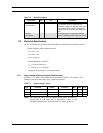
a. V
iMAX
means Absolute Maximum Voltage for Input in the period of 0V <VCC <2.0V, Vi (CE) is only
0V~V
iMAX
.
b. The t
pr
and t
pf
are defined as "linear waveform" in the period of 10% to 90% or vice-versa. Even if
the waveform is not "linear waveform," its rising and falling time must be met by this specification.
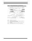
Figure 3-1 Power Up/Power Down Timing for Systems supporting RESET
V
CC
2V
V
IH
V
CC
Min.
t
rec
-CE1, -CE2
ts (Hi-z Reset)
Hi-z
t
pf
t
W
(Reset)
V
CC
Min.
t
W
(Reset)
Reset
t
pr
t
SU
(V
CC
)
-CE1, -CE2
t
SU
(Reset)
t
SU
(Reset)
th (Hi-z Reset)
Hi-z
2V
V
IH
02/07, Rev. 12.0 3-10 © 2007 SanDisk Corporation
V