


CT4xx Series Quick Guide Pg 3 CT4xx Series Quick Guide Pg 10
Connecting The Printer
6. When you send the print job to the printer and it does not respond, and
there is no error message on the PC :
a. Check your data stream for some of the basics. Is your job framed
as follows :
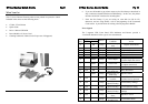
1. Locate a solid flat surface with adequate room to set the printer. Make sure
the Power Module can be located so that the power connecting the cable can
be attached to the printer and the AC Power Cable can be connected to an
AC power outlet.
<ESC>A--DATA--<ESC>Z
b. Verify that you have included all required parameters in the data
stream.
c. Verify the following :
2. The location should be near the host or computer terminal. The maximum
distance is :
i. You have not typed a ‘0’ (zero) for an ‘O’ (letter) or vice-versa.
ii. You have not missed any <ESC> characters where they are
needed.
- 10 feet for the Parallel interface. To fully utilise the capabilities of
the printer, a cable meeting IEEE 1284 specifications must be used.
iii. Make sure all printer command codes are in Capital Letters.
- 18 feet for the optional Serial RS232 interface.
- 10 feet for the optional USB interface without hub.
7. If you have checked all of the above and the printer is still not printing,
you may want to try a Buffer Hex Dump to determine what (if anything)
the printer is receiving from your computer.
- The optional 10baseT Ethernet Interface depends upon the LAN
cabling.
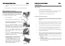
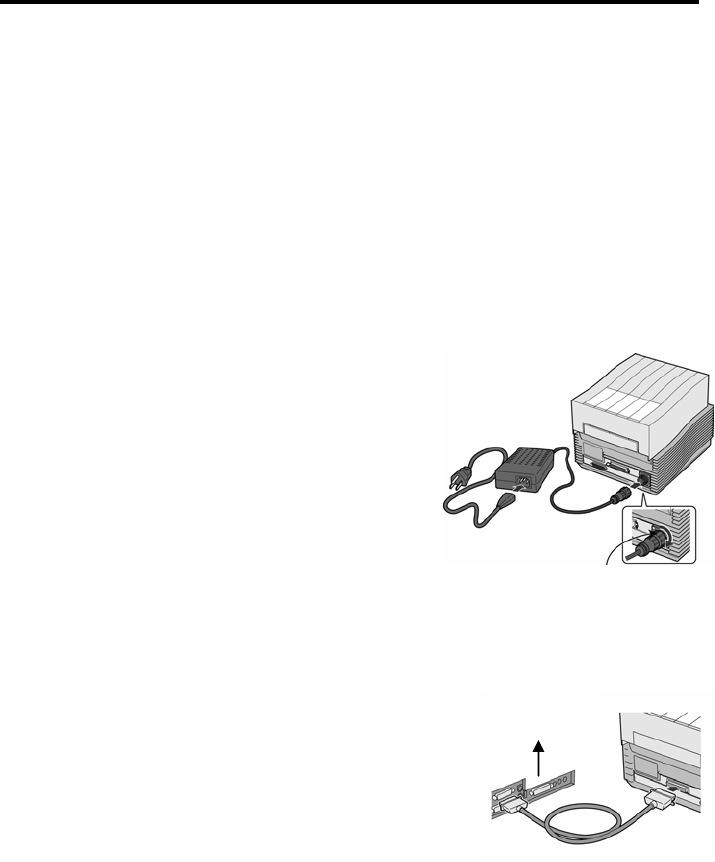
3. Make sure the power switch on the
Operator Panel is in the OFF (0) position
and place the Power Module in a safe and
secure location, taking into consideration
the location of the AC outlet and the host
in relation to the printer.
Input Power
Connector
Using the RS232C Serial Interface
1. Is the RS232C Serial Cable connected securely to your serial port on the
PC (DB-25S or DB-9S Male) and to the RS232C connector on the
printer?
2. Is the cable defective? At the very least, you should be using a “Null
Modem Cable” which crosses pins in a specific manner. This should
enable your printer to print. But we recommend that you eventually use
a cable built to specifications as described in Section 5 of the Operator
& Technical Reference Manual : Interface Specifications.
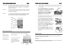
4. Connect the Input Power connector to the
printer. This connector is keyed and must
be turned approximately ¾ turn clockwise
to secure it to the printer.
5. Connect the AC Power Cable to the proper AC Outlet supply.
3. Is the RS232 Interface option installed in the printer? DSW-8 must be in
the OFF Position to enable the Optional Interface.
6. Connect the interface cable to the host system.
A parallel IEEE1284 interface cable must be
used to realise the high data transfer rate of the
printer’s parallel port. If an optional interface
is installed, the appropriate cable should be
used.
Host IF
Connector
4. Check for obvious errors in the data stream. Is the data properly framed
with the <ESC>A and <ESC>Z commands?
5. If after sending your job to the printer, it only “beeps’ and displays an
error message of the 7-segment display, you may have a configuration
problem. There may be some inconsistencies with the Baud Rate,
Parity, Data Bits, or Stop Bits in relation to your host computer. If you
are confused as to what the printer’s current RS232 settings are, print a
self test label (refer to Section 2 of the Operator & Technical Reference
Manual). It contains a list of all the current printer configuration
settings.
7. Load the ribbon and media following the
instructions in the next section
8. Configure the printer for label width and operating mode by referring to the
Operator & Technical Reference Manual – Section 2.