


CT4xx Series Quick Guide Pg 4 CT4xx Series Quick Guide Pg 9
Troubleshooting
9. Apply power to the printer by placing the AC Power switch in the ON (1)
position.
Initial Checklist
10. Print a test label to verify the printer is set up and operating correctly.
1. Is the Printer powered up and ONLINE?
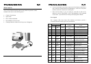
Ribbon Loading (CT4xxTT only)
2. Do any of the Front Panel LEDs indicate an error condition? If the Error
LED is lighted, it may mean the print head assembly is open.
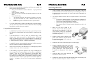
The SATO CT Series ribbons come shrink-wrapped with a
12” (305mm) leader pre-attached to a take-up core. There
are 3 widths of ribbon available for the CT Series printers :
4.3” (110mm), 3” (76mm) & 1.75” (45mm).
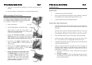
1. Power off the printer.
2. Open the Top Cover by pressing the release
points located on each side of the printer. This
releases the cover latch and allows it to swing upward
on the rear mounted hinge points.
3. Release the Print Head Assembly by pressing the
Head Latch to the rear. This allows the assembly to
rotate upwards to the left allowing easy access for
ribbon routing. Rotate the assembly until it is vertical.
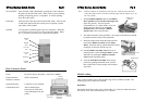
Head Latch
Ribbon
Ass’y Latch
Ribbon Position
Button
3. Is the Print Head in the down and latched position?
Using the IEEE 1284 Parallel Interface
1. Is the IEEE 1284 printer cable connected securely to your parallel port
(DB-25S Female) on the PC and to the Parallel Interface connector on
the printer?
Warning : Never connect or disconnect interface cables (or use a switch
box) with power applied to either the printer or the host. This may
cause damage to the interface circuitry and is not covered by warranty.
2. Does the Parallel interface cable used meet IEEE 1284 specifications?
3. Is there more than 1 parallel interface port on your PC (LPT1, LPT2,
etc.)? If so, make sure you are sending data out of the correct port.
4. Press down on the Ribbon Assembly Latch. This
allows the Paper Roller to swing downwards for
ribbon routing.
5. Press down on the Ribbon Positioning button while
simultaneously pulling upwards on the Ribbon
Spindle Unit, which should slide off.
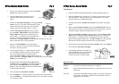
Paper Roller
Ribbon Supply
Spindle
Ribbon Take-Up
Spindle
4. Is the IEEE 1284 interface selected? DSW-8 must be in the ON position
to enable the Parallel interface.
5. When you send the print job to the printer and it does not respond, do
you get an error message on your PC that says “Device Fault” or
something similar? This may mean that the computer does not know the
printer is there. Verify that :
a. Both ends of the cable are securely inserted into their respective
connectors.
6. Remove the shrink-wrap from the ribbon and
unwind approximately 6” off the leader. Press
the Ribbon Supply core all the way onto the
rear spindle of Ribbon Spindle Unit. Press
the attached take-up core on the front spindle.
Make sure each core is fully seated on the
spindles and there is enough ribbon leaders to
go down around the print head
b. The printer is ONLINE
c. The cable is not defective. There are other things that can cause this
error message on your computer, but at this stage, a defective cable
may be one of the reasons.