


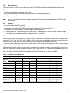
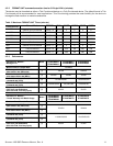
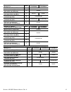

High Endurance 2.5” Models -
Limited Warranty with Media Usage
Notes
ST400FM0093
ST400FM0103
ST200FM0093
ST200FM0103
ST100FM0093
ST100FM0103
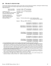
Maximum Burst Transfer Rate 1200MB/s
Peak sequential 128KB read/write
data transfer rate (MB/s max)
[1]
750/500 750/400
Sustained sequential 128KB read/
write data transfer rate (MB/s)
[1]
Peak 4KB random read/write
command rate (IOPs)
[2]
110,000/50,000 110,000/50,000
Sustained 4KB random read/write
command rate (IOPs)
[2]
Sustainable 4KB Random combined
IOPS for 5 year Endurance
(65%/35% R/W, 70% Duty Cycle)
[3] 70,000 60,000
SEAGATE 1200 SSD PRODUCT MANUAL, REV. A 13
[1] Testing performed at Queue Depth = 128, Sequentially Preconditioned drive, using IOMeter 2006.7.27.
[2] Testing performed at Queue Depth = 128, Randomly Preconditioned drive, using IOMeter 2006.7.27.
[3] Testing performed at Queue Depth = 128, Non-Preconditioned drive, using IOMeter 2006.7.27.
Note. IOMeter is available at h
ttp://www.iometer.org/ or http://sourceforge.net/projects/iometer/.
IOMeter is licensed under the Intel Open Source License and the GNU General Public License. Intel does not
endorse any IOMeter results.
Peak performance is defined as the typical best case performance that the product will be able to achieve when
the product is preconditioned as mentioned and host commands are aligned on 4KB boundaries.
Sustained performance is defined as the worst case performance that the product will be able to achieve when the product is
preconditioned
as mentioned and host commands are aligned on 4KB boundaries. For models that support Lifetime
Endurance Management, write values also take into account the worst case performance throttling that may occur to ensure
the product meets specified reliability specifications.
Due to the nature of Flash memory technologies there are many factors that can result in values different than those stated
in this specification. Some discrepancies can be caused by bandwidth limitations in the host adapter, operating system, or
driver limitations. It is not the intent of this manual to cover all possible causes of performance discrepancies.
When evaluating performance of SSD devices, it is recommended to measure performance of the device in a method that
resembles the targeted application using real world data and workloads. Test time should also be adequately large to ensure
that sustainable metrics and measures are obtained.
4.3 START/STOP TIME
The drive accepts the commands listed in the SAS Interface Manual less than 3 seconds after DC power has been applied.
If the drive receives a NOTIFY (ENABLE SPINUP) primitive through either port and has not received a START STOP UNIT
command with the START bit equal to 0, the drive becomes ready for normal operations within 10 seconds (excluding the
error recovery procedure).
If the drive receives a START STOP UNIT command with the START bit equal to 0 before receiving a NOTIFY (ENABLE
SPINUP) primitive, the drive waits for a START STOP UNIT command with the START bit equal to 1. After receiving a
START STOP UNIT command with the START bit equal to 1, the drive waits for a NOTIFY (ENABLE SPINUP) primitive.
After receiving a NOTIFY (ENABLE SPINUP) primitive through either port, the drive becomes ready for normal operations
within 10 seconds (excluding the error recovery procedure).
If the drive receives a START STOP UNIT command with the START bit and IMMED bit equal to 1 and does not receive a
NOTIFY (ENABLE SPINUP) primitive within 5 seconds, the drive fails the START STOP UNIT command.
The START STOP UNIT command may be used to command the drive to stop. Stop time is 3 seconds (maximum) from
removal of DC power. SCSI stop time is 3 seconds. There is no power control switch on the drive.