


SEAGATE 1200 SSD PRODUCT MANUAL, REV. A 69
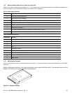
Table 24 Micro SAS pin descriptions
P
IN SIGNAL NAME SIGNAL TYPE PIN SIGNAL NAME SIGNAL TYPE
S1 Port A Ground P1* 3.3 Volts
S2* +Port A_in Diff. input pair P2 3.3 Volts charge
S3* -Port A_in P3 Ground
S4 Port A Ground P4 Ground
S5* -Port A_out Diff output pair P5 5 Volts charge
S6* +Port A_out P6* 5 Volts
S7 Port A Ground P7* Reserved
S8 Port B Ground P8* NC (reserved for Manufacturing diagnostic)
S9* +Port B_in Diff. input pair P9* NC (reserved for Manufacturing diagnostic)
S10* -Port B_in
S11 Port B Ground A1* Vendor specific
S12* -Port B_out Diff output pair A2* Vendor specific
S13* +Port B_out
S14 Port B Ground
* - Short pin to support hot plugging
NC - No connection in the drive.
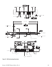
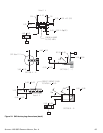
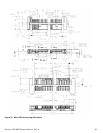
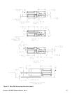
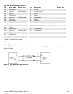
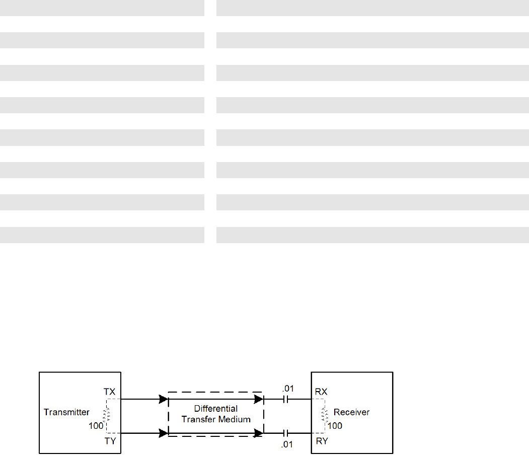
11.4.6 SAS transmitters and receivers
A typical SAS differential copper transmitter and receiver pair is shown in Figure 27. The receiver is AC coupling to eliminate
ground shift noise.
Figure 27. SAS transmitters and receivers