


Barracuda ES.2 FC Product Manual, Rev. B
23
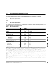
6.0 Physical/electrical specifications
This section provides information relating to the physical and electrical characteristics of the drive.
6.1 AC power requirements
None.
6.2 DC power requirements
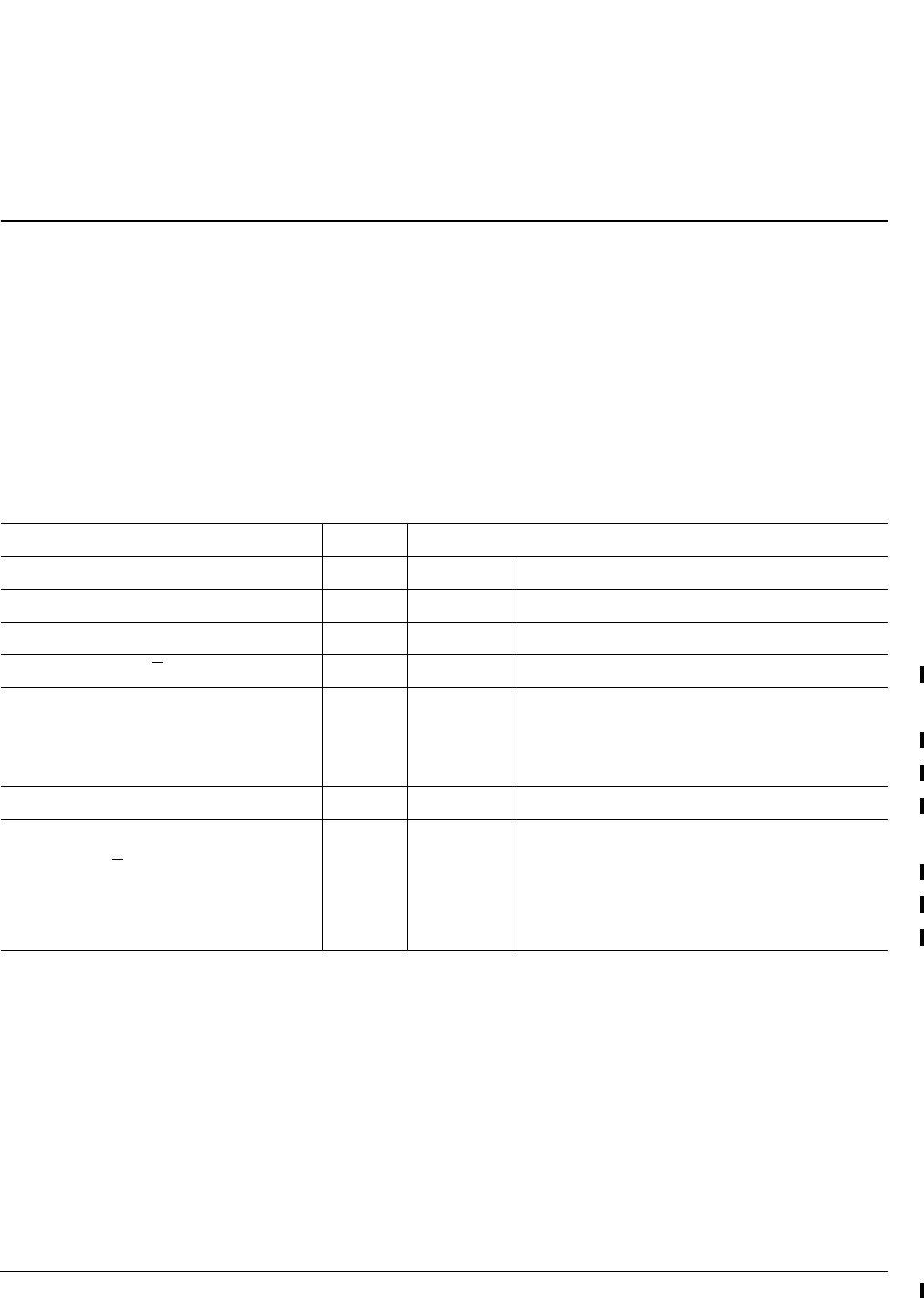
The voltage and current requirements for a single drive are shown below. Values indicated apply at the drive
connector. Notes are shown following table 2.
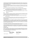
[1] Measured with average reading DC ammeter. Instantaneous +12V current peaks will exceed these val-
ues. Power supply at nominal voltage. N (number of drives tested) = 6, 35 Degrees C ambient.
[2] For +12 V, a –10% tolerance is allowed during initial spindle start but must return to ±5% before reaching
10,000 RPM. The ±5% must be maintained after the drive signifies that its power-up sequence has been
completed and that the drive is able to accept selection by the host initiator.
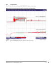
[3] See +12V current profiles in Figure 1.
[4] This condition occurs when the Motor Start option is enabled and the drive has not yet received a Start
Motor command.
[5] See paragraph 6.2.1, "Conducted noise immunity." Specified voltage tolerance includes ripple, noise, and
transient response.
[6] During idle, the drive heads are relocated every 60 seconds to a random location within the band from
Table 2: DC power requirements
4 Gbit
Notes (Amps) (Amps)
Voltage +5V +12V [2]
Regulation [5] ±5% ±5% [2]
Avg idle current DCX
[1] [6] 0.75 0.50
Maximum starting current
(peak DC) DC 3σ [3] 1.00 2.00
(peak AC) AC 3σ [3] 1.15 3.23
Delayed motor start (max) DC 3σ [1] [4] 0.65 0.04
Peak operating current:
Typical DCX [1] 0.69 0.77
Maximum DC 3σ [1] 0.71 0.82
Maximum (peak) DC 3σ 1.13 1.67