


58
Barracuda ES.2 FC Product Manual, Rev. B
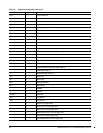
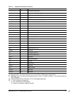
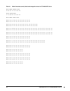
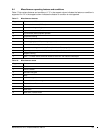
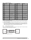
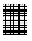
Table 19: FC-SCA pin descriptions
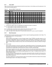
*Short pins in mating backpanel connector.
[1] This pin may be connected to external logic to detect the presence of the drive. The drive connects this
pin to the common ground.
[2] Pins 9, 10, 17, 18, and 39 are option select pins and are tied high by the drive circuitry. The preferred elec-
trical connection at the backplane is either open or grounded (open for the ‘1’ setting, grounded for the ‘0’
setting). Alternatively, these pins may be driven by a 3.3V logic device, pulled up to 3.3V through a pull-up
resistor (recommended size of 10k ohm), or grounded through some other means.
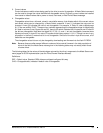
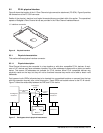
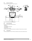
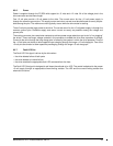
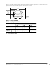
9.5.5 FC-AL transmitters and receivers
A typical FC-AL differential copper transmitter and receiver pair is shown in Figure 9. The receiver is required
to provide the AC coupling to eliminate ground shift noise.
Figure 9. FC-AL transmitters and receivers
Pin Signal name Signal type Pin Signal name Signal type
1* -EN bypass port A Low Voltage TTL output 21 12 Volts charge
2* 12 Volts 22 Ground
3* 12 Volts 23 Ground
4* 12 Volts 24* +Port A_in FC Diff. input pair
5* -Parallel ESI 25* -Port A_in
6* Ground
[1]
26 Ground
7* Active LED out Open collector out 27* +Port B_in FC Diff. input pair
8* Reserved 28* -Port B_in
9* Start_1
[2]
TTL input 29 Ground
10* Start_2
[2]
TTL input 30* +Port A_out FC Diff. output pair
11* -EN bypass port B Low Voltage TTL output 31* -Port A_out
12* SEL_6 TTL input/output 32 Ground
13* SEL_5 TTL input/output 33* +Port B_out FC Diff. output pair
14* SEL_4 TTL input 34* -Port B_out
15* SEL_3 TTL input/output 35 Ground
16* Fault LED out Open collector out 36 SEL_2 TTL input/output
17* DEV_CTRL_CODE_2
[2]
TTL input 37 SEL_1 TTL input/output
18* DEV_CTRL_CODE_1
[2]
TTL input 38 SEL_0 TTL input/output
19* 5 Volts 39 DEV_CTRL_CODE_0
[2
TTL input
20* 5 Volts 40 5 Volts charge
TY
.01
Differential
Transfer Medium
.01
Transmitter
TX
RY
Receiver
RX
100
100