


60
Barracuda ES.2 FC Product Manual, Rev. B
9.5.8 Active LED Out
The Active LED Out signal is driven by the drive as indicated in Table 20.
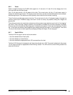
The Active LED Out signal is designed to pull down the cathode of an LED. The anode is attached to the
proper +5 volt supply through an appropriate current limiting resistor. The LED and the current limiting resistor
are external to the drive.
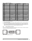
9.5.9 Enable port bypass signals
The – Enable Bypass Port A (– EN BYP Port A) and – Enable Bypass Port B (– EN BYP Port B) signals control
the port bypass circuits (PBC) located external to the disc drive. The PBC allows a loop to remain functional in
the event of a drive failure or removal. When these signals are active, low, the PBC bypasses the drive on the
associated port. When an Enable Bypass signal is active, the corresponding Port Bypass LED signal in con-
nector J1 is driven low by the disc drive. A pull down resistor, 1K, located with the PBC should be used to
insure the bypass is enabled if the disc drive is not installed.
The Enable Bypass signal is active under failing conditions within the drive, on detection of the Loop Port
Bypass primitive sequence, or on removal of the drive. In the bypass state the drive continues to receive on the
inbound fibre. Enable Bypass may be deactivated by detection of a Loop Port Enable primitive sequence if the
drive has completed self-test and a hardware failure is not present.
Failure modes detected by the disc drive that will enable bypass include:
• Transmitter/receiver wrap test failure
• Loss of receive clock
• Loss of transmission clock
• Drive interface hardware error
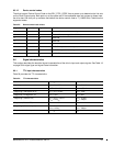
9.5.10 Motor start controls
The drive’s motor is started according to the Start_1 and Start_2 signals described in Table 21. The state of
these signals can be wired into the backplane socket or driven by logic on the backplane.
Table 20: Active LED Out conditions
Normal command activity LED status
Spun down and no activity Slow blink (20% on and 80% off a 2 sec cycle)
Spun down and activity (command executing) On
Spun up and no activity On
Spun up and activity (command executing) Off
Spinning up or down Blinks steadily (50% on and 50% off)
Format in progress, each cylinder change Toggles on/off
Table 21: Motor start control signals
Case Start_2 Start_1 Motor spin function
1 Low Low Motor spins up at DC power on.
2 High Low Motor spins up only when SCSI Start command is received.
3 Low High Motor spins up after a delay of 12 seconds times the modulo 8 value
of the numeric SEL ID of the drive from DC power on.
4 High High The drive will not spin up.