


64
Barracuda ES.2 FC Product Manual, Rev. B
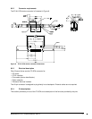
9.6.2 LED driver signals
Fault and Active LED signals are located in the FC-SCA connector (J1). See Table 25 for the output character-
istics of the LED drive signals.
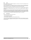
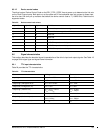
9.6.3 FC Differential output
The serial output signal voltage characteristics are provided in Table 26. The outputs are not AC coupled in
order to deliver maximum signal without rise and fall time degradation. You must AC couple the receiver to iso-
late potentially different DC characteristics of the outputs and the receiver.
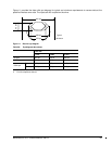
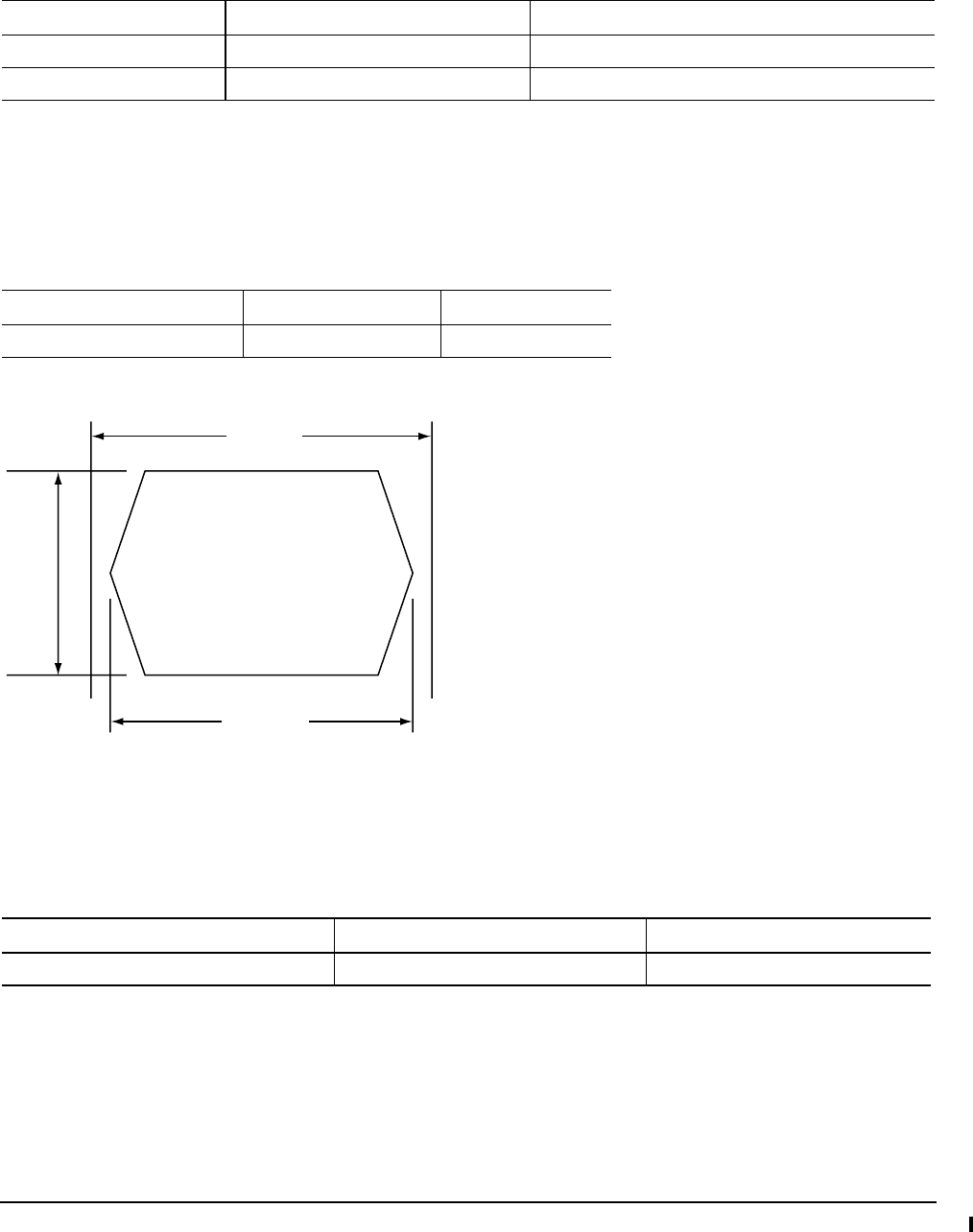
Figure 10 provides the data output valid eye diagram relative to the bit cell time.
Figure 10. Transmit eye diagram
9.6.4 FC Differential input
The serial input signal voltage characteristics are provided in Table 27.
Table 25: LED drive signal
State Current drive available Output voltage
LED off, high 0 < I
OH
< 100µA
LED on, low I
OL
< -30 mA 0 < V
OL
< 0.8V
Table 26: FC Differential output characteristics
Description Parameter Notes
Serial output voltage swing 600 < V
out
< 1300 mV Centered at 1.32V
Table 27: FC Differential input characteristics
Description Parameter Notes
Serial input voltage swing 200 < V
in
< 1.300 mV AC coupled
Bit Time
Vout (mv)
XMIT Eye