


38
Barracuda ES.2 FC Product Manual, Rev. B
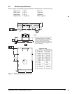
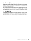
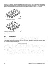
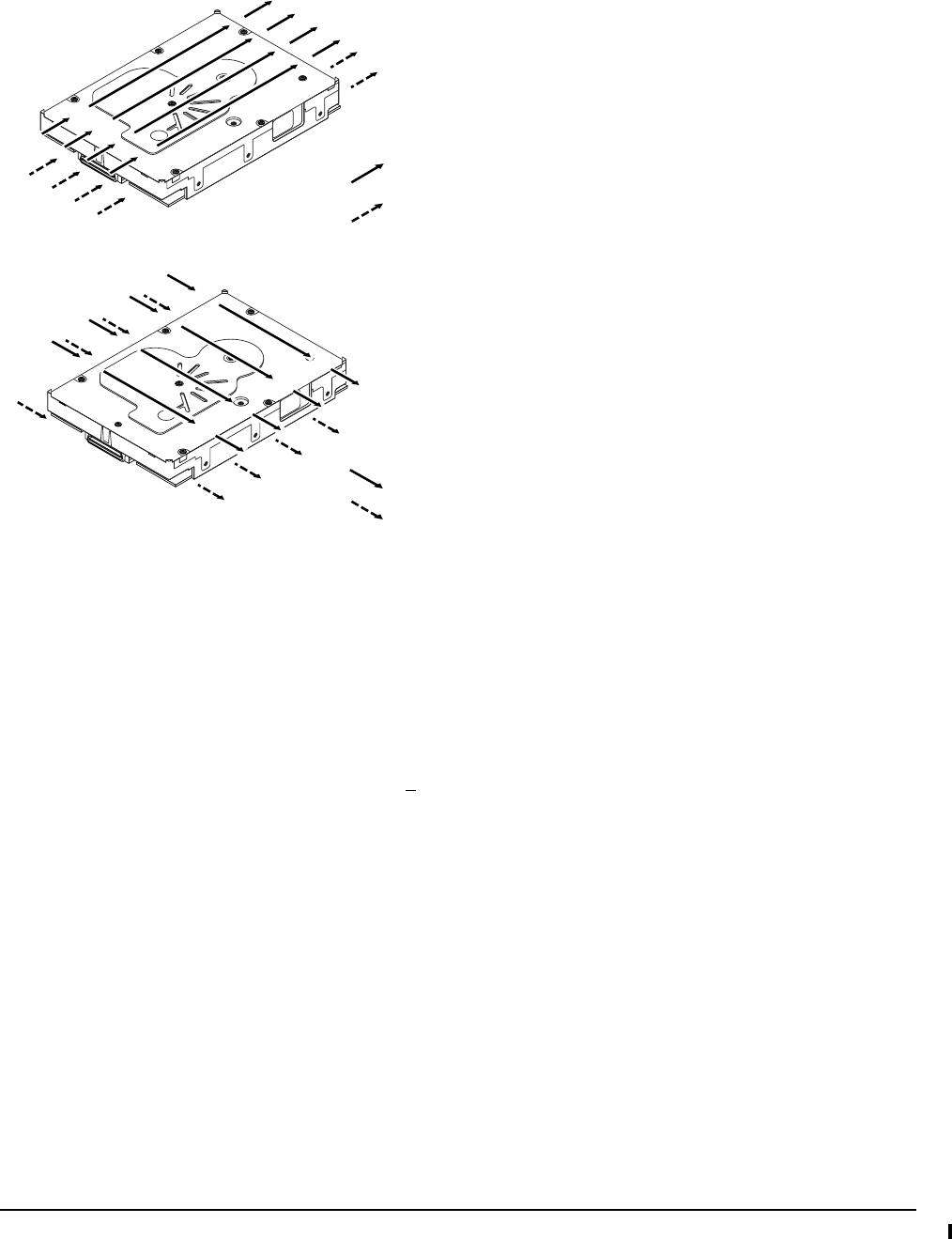
If forced air is necessary, possible air-flow patterns are shown in Figure 5. The air-flow patterns are created by
fans either forcing or drawing air as shown in the illustrations. Conduction, convection, or other forced air-flow
patterns are acceptable as long as the temperature measurement guidelines of Section 6.4.1 are met.
Figure 5. Air flow
8.4 Drive mounting
Mount the drive using the bottom or side mounting holes. If you mount the drive using the bottom holes, ensure
that you do not physically distort the drive by attempting to mount it on a stiff, non-flat surface.
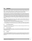
The allowable mounting surface stiffness is 80 lb/in (14.0 N/mm). The following equation and paragraph define
the allowable mounting surface stiffness:
where K is the mounting surface stiffness (units in lb/in or N/mm) and X is the out-of-plane surface distortion
(units in inches or millimeters). The out-of-plane distortion (X) is determined by defining a plane with three of
the four mounting points fixed and evaluating the out-of-plane deflection of the fourth mounting point when a
known force (F) is applied to the fourth point.
Note. Before mounting the drive in any kind of 3.5-inch to 5.25-inch adapter frame, verify with Seagate
Technology that the drive can meet the shock and vibration specifications given herein while
mounted in such an adapter frame. Adapter frames that are available may not have a mechanical
structure capable of mounting the drive so that it can meet the shock and vibration specifications
listed in this manual.
Above unit
Under unit
Note. Air flows in the direction shown (back to front)
or in reverse direction (front to back)
Above unit
Under unit
Note. Air flows in the direction shown or
in reverse direction (side to side)
K x X = F < 15lb = 67N