


SV35 Series SATA Product Manual, Rev. B
25
3.3 Configuring the drive
Each drive on the Serial ATA interface connects in a point-to-point configuration with the Serial ATA host
adapter. There is no master/slave relationship because each drive is considered a master in a point-to-point
relationships. If two drives are attached on one Serial ATA host adapter, the host operating system views the
two devices as if they were both “masters” on two separate ports. This means both drives behave as if they are
Device 0 (master) devices.
Serial ATA drives are designed for easy installation. It is usually not necessary to set any jumpers on the drive
for proper operation; however, if you connect the drive and receive a “drive not detected” error, your SATA-
equipped motherboard or host adapter may use a chipset that does not support SATA speed autonegotiation. If
you have a motherboard or host adapter that does not support autonegotiation:
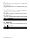
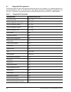
• Configure the jumper block with a jumper as shown in Figure 4 below to limit the data transfer rate to 1.5 Gbits
per second (and leave the drive connected to the SATA-equipped motherboard or host adapter that doesn’t
support autonegotiation) or
• Install a SATA host adapter that supports autonegotiation, set the drive jumper block set to “3 Gbits per second
operation” (see Figure 4 below), and connect the drive to that adapter. This option has the benefit of not limiting
the drive to a 1.5 Gbits/sec transfer rate.
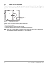
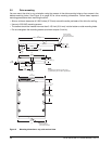
Figure 4 Serial ATA jumper block and connectors
3.4 Serial ATA cables and connectors
The Serial ATA interface cable consists of four conductors in two differential pairs, plus three ground connec-
tions. The cable size may be 30 to 26 AWG with a maximum length of one meter (39.37 inches). See Table 6
for connector pin definitions. Either end of the SATA signal cable can be attached to the drive or host.
For direct backplane connection, the drive connectors are inserted directly into the host receptacle. The drive
and the host receptacle incorporate features that enable the direct connection to be hot pluggable and blind
mateable.
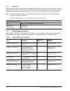
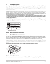
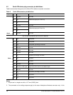
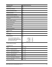
For installations which require cables, you can connect the drive as illustrated in Figure 5.
Figure 5 Attaching SATA cabling
Each cable is keyed to ensure correct orientation. SV35 Series SATA drives support latching SATA connectors.
Jumper block
SATA interface connector
SATA power connector
Limit data transfer rate to
1.5 Gbits per second
3.0 Gbits per second operation
Power cable
S
ignal cable
Signal connector
Power connector