


26
SV35 Series SATA Product Manual, Rev. B
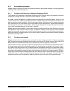
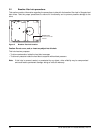
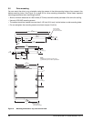
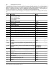
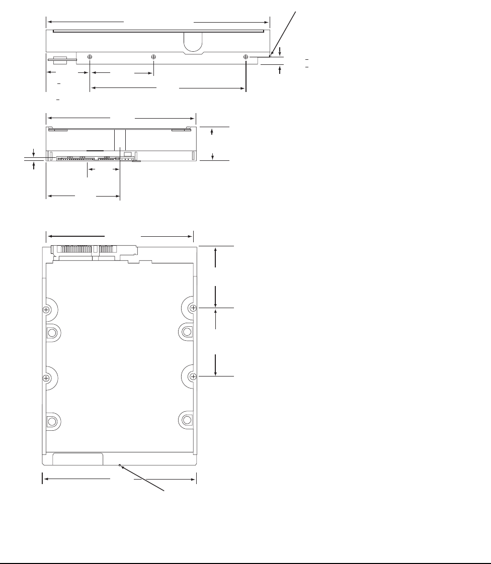
3.5 Drive mounting
You can mount the drive in any orientation using four screws in the side-mounting holes or four screws in the
bottom-mounting holes. See Figure 6 on page 26 for drive mounting dimensions. Follow these important
mounting precautions when mounting the drive:
• Allow a minimum clearance of 0.030 inches (0.76 mm) around the entire perimeter of the drive for cooling.
• Use only 6-32 UNC mounting screws.
• The screws should be inserted no more than 0.150 inch (3.81 mm) into the bottom or side mounting holes.
• Do not overtighten the mounting screws (maximum torque: 6 inch-lb).
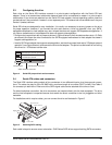
Figure 6 Mounting dimensions—top, side and end view
4.000
(101.6)
5.787 (146.9898) max.
1.028 max
(26.111 max)
2.00
(50.80)
1.638
(41.605)
4.000
(101.6)
2 x 1.750
(2 x 44.45)
2 x 3.750
(2 x 95.25)
C
L
of drive
[1]
Notes:
Dimensions are shown in inches (mm).
[1] Dimensions per SFF-8301 specification
[1]
[1]
[1]
1.122
+ .020
(28.499
+ .508)
[1]
[1]
[1]
[1]
C
L
of conn. Datum B
.814
(20.676)
.138
(
3.505)
.250 + .015
(6.35 + .381)
(3x both sides)
4.000
(101.6)
2 x 1.625
(2 x 41.28)
[1]
Recommended
case temperature
measurement location
Recommended
case temperature
measurement locatio
n