


39
E
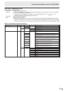
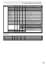
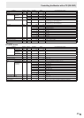
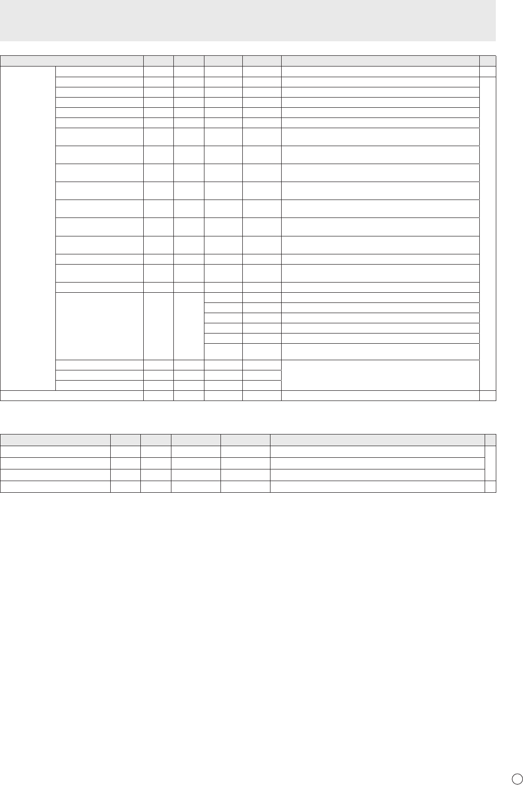
Function
Command Direction
Parameter Reply Control/Response contents *
ADVANCED AUTO
AGIN W 1 When the input mode is D-SUB[RGB], DVI-I (analog).
-
ANALOG GAIN
ANGA WR 0-127 0-127 When the input mode is D-SUB[RGB], DVI-I (analog).
○
ANALOG OFFSET
ANOF WR 0-127 0-127 When the input mode is D-SUB[RGB], DVI-I (analog).
3D-NR (AV input) TDNR WR 0-2 0-2 0: OFF, 1: LOW, 2: HIGH
MPEG-NR (AV input) MPNR WR 0-1 0-1 0: OFF, 1: ON
3D-Y/C YCSP WR 0-1 0-1 0: OFF, 1: ON (When the input mode is D-SUB[VIDEO])
RGB INPUT RANGE
(HDMI1[AV])
AHDR WR 0-2 0-2 0: AUTO, 1: FULL, 2: LIMITED
RGB INPUT RANGE
(HDMI1[PC])
PHDR WR 0-2 0-2 0: AUTO, 1: FULL, 2: LIMITED
RGB INPUT RANGE
(HDMI2[AV])
AH2R WR 0-2 0-2 0: AUTO, 1: FULL, 2: LIMITED
RGB INPUT RANGE
(HDMI2[PC])
PH2R WR 0-2 0-2 0: AUTO, 1: FULL, 2: LIMITED
RGB INPUT RANGE
(DVI-I)
PDVR WR 1-2 1-2 1: FULL, 2: LIMITED
RGB INPUT RANGE
(D-SUB)
PDSR WR 1-2 1-2 1: FULL, 2: LIMITED
RGB INPUT RANGE
(DisplayPort)
PDPR WR 0-2 0-2 0: AUTO, 1: FULL, 2: LIMITED
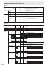
LOCAL DIMMING LODI
WR 0-3 0-3 0: OFF, 1: LOW, 2: MIDDLE, 3: HIGH
POWER LIMITER PWSV
WR 0-2 0-2 0: OFF, 1: MODE1, 2: MODE2
“ERR” when LOCAL DIMMING is not set to HIGH.
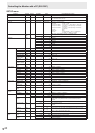
ACTIVE CONTRAST (AV input)
ACNT WR 0-1 0-1 0: OFF, 1: ON
DISPLAY COLOR PATTERN PTDF WR
0 0 No pattern display.
1 1 White single color pattern display.
2 2 Red single color pattern display.
3 3 Green single color pattern display.
4 4 Blue single color pattern display.
99 99 Red/green/blue mixed color pattern display.
Set each color's level with RED, GREEN, BLUE.
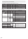
DISPLAY COLOR PATTERN (R)
PTDR WR 0-15 0-15 “ERR” when PTDF is not set to 99.
DISPLAY COLOR PATTERN (G)
PTDG WR 0-15 0-15
DISPLAY COLOR PATTERN (B) PTDB WR 0-15 0-15
RESET ARST W 2
-
AUDIO menu
Function
Command Direction
Parameter Reply Control/Response contents *
TREBLE AUTR WR -5-5 -5-5
○
BASS AUBS WR -5-5 -5-5
BALANCE AUBL WR -10-10 -10-10
RESET ARST W 3
-
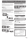
Controlling the Monitor with a PC (RS-232C)