


44
E
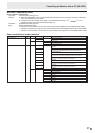
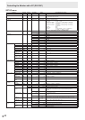
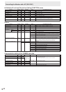
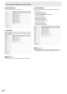
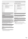
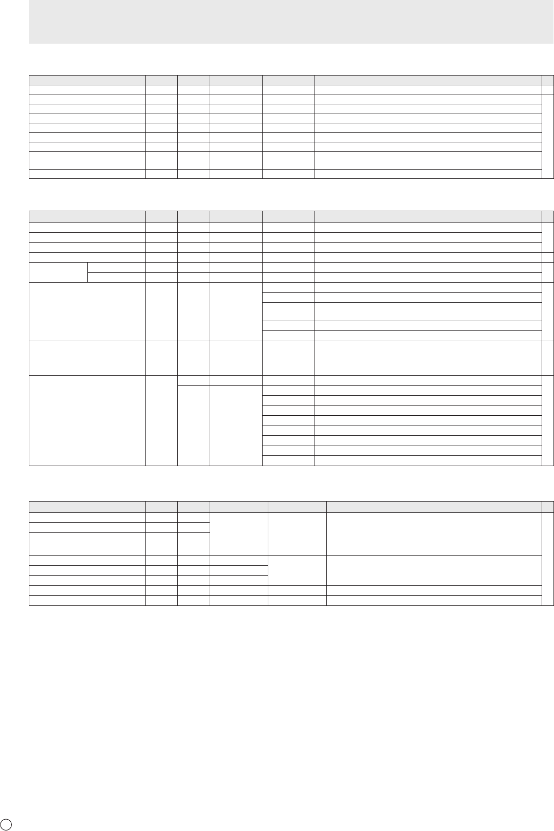
Initialization/Functional Restriction Setting (FUNCTION) menu
Function
Command Direction
Parameter Reply Control/Response contents *
ALL RESET RSET W 0-1 0: ALL RESET 1, 1: ALL RESET 2 -
ADJUSTMENT LOCK ALCK WR 0-2 0-2 0: OFF, 1:ON1, 2:ON2
○
ADJUSTMENT LOCK TARGET ALTG WR 0-2 0-2 0: REMOTE CONTROL, 1: MONITOR BUTTONS, 2: BOTH
OSD DISPLAY LOSD WR 0-2 0-2 0: ON1, 1: OFF, 2: ON2
LED OFLD WR 0-1 0-1 0: ON, 1: OFF
TEMPERATURE ALERT TALT WR 0-2 0-2 0: OFF, 1: OSD & LED, 2: LED
POWER BUTTON PBTN WR 0-1 0-1 0: MONITOR, 1: CONTROLLER
CONTROLLER INPUT PCIP WR 0-4 0-4 0: D-SUB, 1: DisplayPort, 2: HDMI1, 3: HDMI2, 4: DVI-I
(”ERR” when MONITOR is selected for POWER BUTTON.)
STATUS ALERT SALT WR 0-2 0-2 0: OFF, 1: OSD & LED, 2: LED
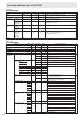
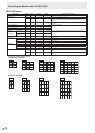
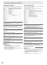
Others
Function
Command Direction
Parameter Reply Control/Response contents *
SCREEN SIZE (PC) WIDE WR 1-5 1-5 1: WIDE, 2: NORMAL, 3: Dot by Dot, 4: ZOOM1, 5: ZOOM2
○
SCREEN SIZE (AV) WIDE WR 1-5 1-5 1: WIDE, 2: ZOOM1, 3: ZOOM2, 4: NORMAL, 5: Dot by Dot
VOLUME VOLM WR 0-31 0-31
MUTE MUTE WR 0-1 0-1 0: OFF, 1: ON -
INFORMATION MODEL INF1 R Value
●
SERIAL NO SRNO R Value
TEMPERATURE SENSOR DSTA R 0 Internal temperature normal
●
1 Internal temperature abnormal has occurred and the monitor is in standby mode
2 Internal temperature abnormal occurred (To delete the information of temperature
abnormal, turn off the main power.)
3 Internal temperature abnormal has occurred and backlight brightness is dimmed
4 Temperature sensor abnormal
TEMPERATURE ACQUISITION ERRT R Value Temperature at temperature sensors 1 through 6 are returned in the following
forms:
[Sensor 1], [Sensor 2], [Sensor 3], [Sensor 4], [Sensor 5], [Sensor 6]
Indicates a temperature sensor abnormality when “126” is returned.
○
CAUSE OF LAST STANDBY MODE STCA W 0 Initialization
●
R 0 No detectable error has occurred
1 Standby mode by POWER button
2 Main power off by the main power switch
3 Standby mode by RS-232C or LAN
4 Input signal waiting mode by No Signal
6 Standby mode by abnormal temperature
8 Standby mode by SCHEDULE setting
20 Standby mode by OFF IF NO OPERATION setting
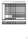
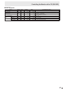
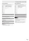
Commands for setting of the GAMMA user data
Function
Command Direction
Parameter Reply Control/Response contents *
RED GAMMA DATA TRANSFER UGRW W aaxxxx
···
xxxxcc
(xxxx: 32 pieces)
aa: 01-16
xxxx: 0000-1023
cc: 00-FF
aa: Block number
xxxx: 32 pieces of user data
cc: Checksum (ASCII data) of the block number and user data
○
GREEN GAMMA DATA TRANSFER UGGW W
BLUE GAMMA DATA TRANSFER UGBW W
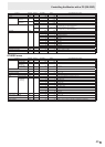
RED GAMMA DATA READ UGRR W 1-16 xxxx
···
xxxx
(xxxx: 32 pieces)
xxxx: 0000-1023
xxxx: User data of 32 pieces
GREEN GAMMA DATA READ UGGR W 1-16
BLUE GAMMA DATA READ UGBR W 1-16
USER DATA INITIALIZE UGRS W 0 Initialize the user data.
USER DATA SAVE UGSV W 0 Save the user data in the monitor.
Controlling the Monitor with a PC (RS-232C)