


9
E
n
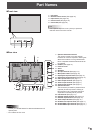
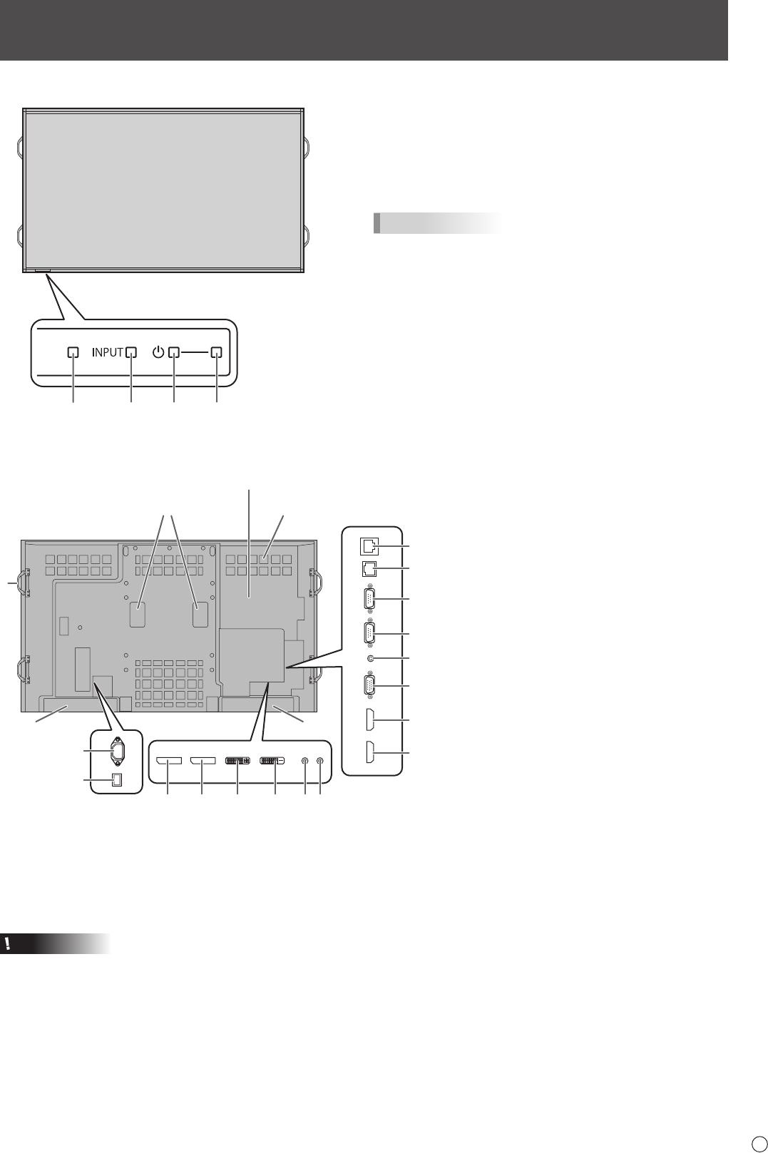
Front view
2
345
1
1. LCD panel
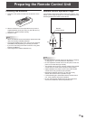
2. Remote control sensor (See page 15.)
3. Input switch (See page 18.)
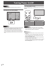
4. Power switch (See page 16.)
5. Power LED (See page 16.)
TIPS
• Use a pointed object such as a pen tip to press the
switches at the front of the monitor.
Part Names
n
Rear view
1
3
2
4
7
6
14
15
16
17
18
19
20
21
8 9 10 11 12 13
5
5
1. Optional attachment section
This section is used to connect optional
hardware for function expansion. Offering this
attachment location is not a guarantee that
future compatible hardware attachments will
be released.
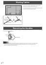
2. Handles (See page 14.)
3. Fan/Fan Cover
4. Vents
5. Speakers
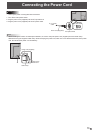
6. AC input terminal (See page 13.)
7. Main power switch (See page 16.)
8. DisplayPort input terminal (See page 11.)
9. DisplayPort output terminal (See page 11.)
10. DVI-I input terminal (See page 11.)
11. DVI-D output terminal (See page 12.)
12. Audio1 input terminal (See page 11.)
13. Audio2 input terminal (See page 11.)
14. Optional terminal
This terminal is provided for possible future
(optional) function expansion. Offering of
this terminal is not a guarantee that future
expanded functionality will be provided.
15. LAN terminal (See page 12.)
16. RS-232C output terminal (See page 12.)
17. RS-232C input terminal (See page 12.)
18. Audio output terminal (See page 12.)
19. PC/AV D-sub input terminal (See page 11.)
20. PC/AV HDMI1 input terminal (See page 11.)
21. PC/AV HDMI2 input terminal (See page 11.)
Caution
• Consult your SHARP dealer for attachment/detachment of
optional parts.
• Do not block the fan cover.